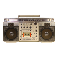
Do you have a question about the Sanyo M7900K and is the answer not in the manual?
| Type | Cassette Player |
|---|---|
| Brand | Sanyo |
| Model | M7900K |
| Power Source | AC or 6 x D batteries |
| Speakers | 2 |
| Frequency Range | FM: 88 - 108 MHz |
Overview of recording system, tape speed, frequency response, and output power.
Details on frequency range, terminal impedance, power source, dimensions, and weight.
Instructions for detaching the back lid and disconnecting associated sockets.
Steps for removing control knobs, screws, and disconnecting various sockets.
Procedure for unscrewing the mechanism and detaching PCBs, including belt and head replacement.
Instructions for replacing recording/playback and erasing heads.
Diagram showing the location of tuner section parts.
Step-by-step alignment process for the FM band, including connections and adjustments.
Alignment procedure for the Medium Wave (MW) band, detailing connections and settings.
Steps for aligning the Shortwave 1 (SW1) band, including signal generator and VTVM connections.
Alignment process for the Shortwave 2 (SW2) band, specifying connections and adjustments.
Cautions for FM adjustment and steps for adjusting the signal meter and FM multiplex.
Instructions for preparing, arranging, and installing the dial rope and pointer.
Procedure to adjust output levels for left and right speaker terminals within ±1 dB.
Steps to adjust the AMSS system for proper blank area detection and tape searching.
Explanation of the AMSS circuit's principle of operation and detailed circuit descriptions.
Details on the AMSS program circuit, channel selection logic, and timing charts.
A diagram showing the overall system architecture and component interconnections.
Procedure for adjusting the head azimuth for optimal sound quality without distortion.
Guidelines for measuring and setting torque tension for tape transport functions.
Method for measuring pinch roller pressure and adjusting it to meet standards.
Procedure to measure and adjust the auto-stop force for reliable tape operation.
Steps to adjust the timing of the main switch relative to pinch roller and capstan.
Specification for mounting the motor pulley at the correct distance from the motor.
An exploded view showing the arrangement of cabinet parts and their identification numbers.
An exploded view detailing the chassis parts and their corresponding key numbers.
List of chassis components.
Components for packing and accessories.
List of hardware components.
List of electrical components.
Comprehensive list of components for the Main Amplifier PCB.
List of components specific to the Power Supply PCB.
Components list for the Headphone PCB.
List of parts for the LED PCB Assembly.
Component list for the AMSS Switch PCB.
Detailed list of components for the Tuner PCB.
A comprehensive list of parts for the cassette mechanism.
List of screws, washers, and other hardware for the mechanism.
List of hardware used in the mechanism assembly.
Illustrated exploded view of the mechanism components (part 1).
Illustrated exploded view of the mechanism components (part 2).
Detailed schematic showing the tuner circuit components and connections.
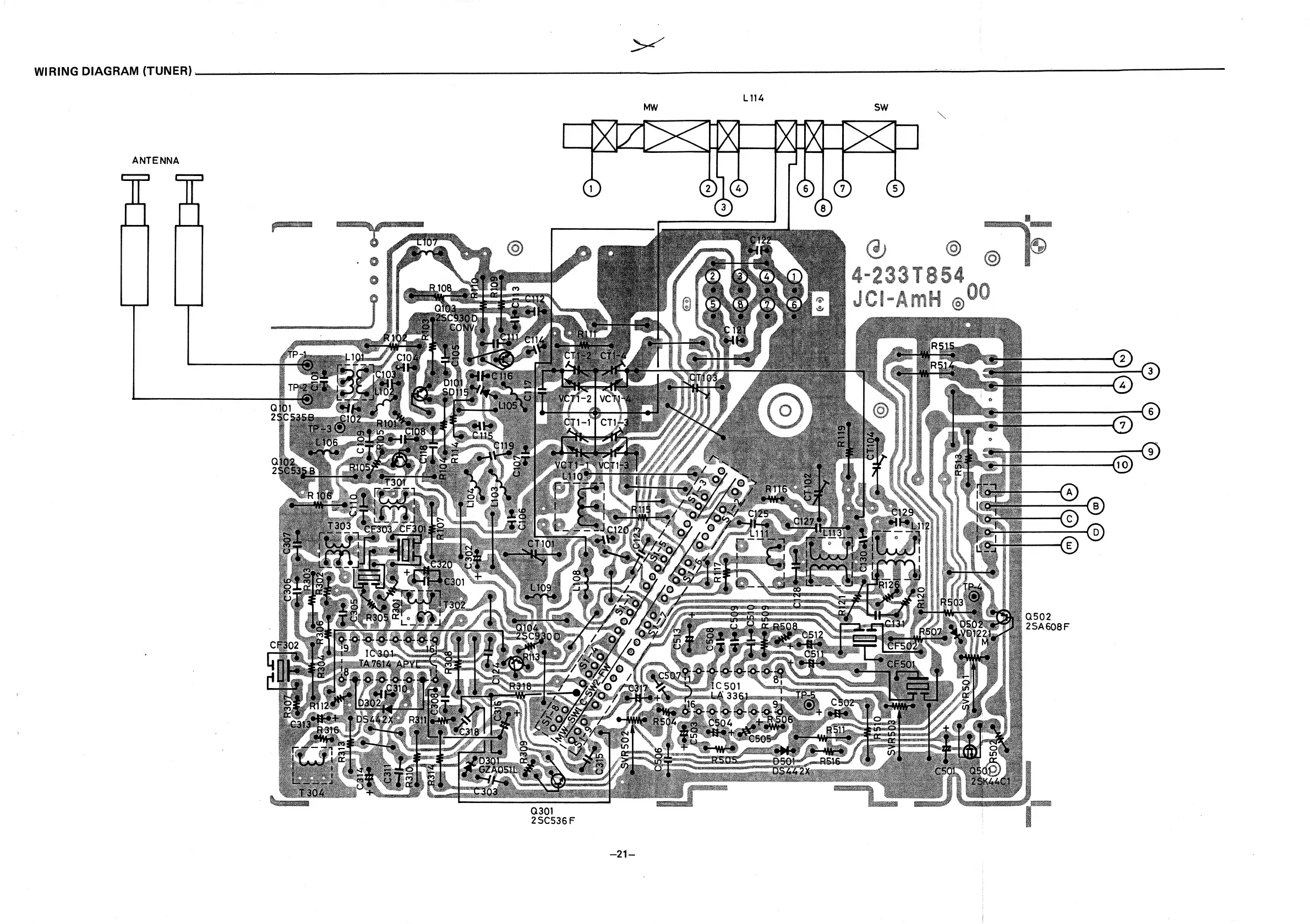
Diagram illustrating the wiring connections for the tuner board.
Schematic showing the amplifier circuit components and their interconnections.
Diagram illustrating the wiring connections for the amplifier board.
Wiring diagram for the control PCB.
Wiring diagram for the AMSS PCB.
Wiring diagram for the AMSS Switch PCB.
Wiring diagram for the Headphone PCB.
Wiring diagram for the LED PCB.
Wiring diagram for the Power Supply PCB.
Detailed schematic of the AMSS circuit, including components and logic.