EasyManua.ls Logo

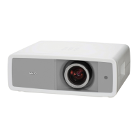
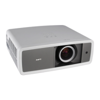
Sanyo PLV-Z4000 Service Manual

Sanyo PLV-Z4000
138 pages
To Next Page IconTo Next Page
To Previous Page IconTo Previous Page
Page #40 background imageLoading...
Page #40 background image
- 40 -
6
Lens shift unit removal.
1. Remove the 4 screws (M3x6) and remove the Lens shift unit.
7
Projection lens removal.
1. Remove the 4 screws (M2.6x6) and remove the Projection lens.
Lens shift unit
Projection lens
Spacer
Optical disassemblies

Table of Contents

Other manuals for Sanyo PLV-Z4000

Questions and Answers:

Sanyo PLV-Z4000 Specifications

General IconGeneral
Projection distance1.2 - 18.4 m
Vertical scan range50 - 100 Hz
Horizontal scan range15 - 80 kHz
Projection technologyLCD
Contrast ratio (typical)-
Lamp power165 W
Light source typeLamp
Service life of light source2000 h
Service life of light source (economic mode)3000 h
Focal length range22.3 - 45.3 mm
Analog signal format systemNTSC, PAL, SECAM
S-Video inputs quantity1
Component video (YPbPr/YCbCr) in2
Dimensions (WxDxH)400 x 346 x 146 mm
Power consumption (typical)250 W
Noise level19 dB
Weight and Dimensions IconWeight and Dimensions
Weight7500 g

Summary

Safety Instructions

SAFETY PRECAUTIONS

Precautions for safe servicing of the projector.

SERVICE PERSONNEL WARNING

Warnings for service personnel regarding lamp and high voltage hazards.

Circuit Protections

Fuse

Details on the projector's fuse type and replacement procedure.

Thermal switch

Function and reset procedure for the internal thermal switch.

Warning temperature and power failure protection

Automatic shutdown mechanisms for overheating and power failure.

Maintenance and Cleaning

Cleaning the Air Filters

Procedure for cleaning and resetting the projector's air filters.

Cleaning the Projection Lens

Instructions for cleaning the projection lens to maintain image quality.

Cleaning the Projector Cabinet

Method for cleaning the projector's exterior cabinet.

Lamp Replacement

LAMP HANDLING PRECAUTIONS

Safety precautions for handling the high-pressure lamp.

How to check lamp used time

Procedure to check the total lamp usage time.

Mechanical Disassemblies

Cabinet top ass'y removal.

Procedure for removing the cabinet top assembly.

AV panel removal.

Procedure for removing the AV panel.

Main PWB removal.

Procedure for removing the main PWB and associated components.

Cabinet front ass'y removal.

Procedure for removing the projector's front cabinet assembly.

Optical Disassemblies

LCD panel / prism ass'y removal.

Procedure for removing the LCD panel and prism assembly.

Optical parts location and direction

Diagram showing the location and orientation of optical parts.

Adjustments

Adjustments after Parts Replacement

Table indicating necessary adjustments after replacing specific parts.

Caution to memory IC replacement

Cautionary advice regarding memory IC replacement.

Optical Adjustment

Contrast adjustment (Polarized glass and Optical filter)

Detailed procedure for contrast adjustment of polarized glass and optical filters.

Electrical Adjustment

Service Adjustment Menu Operation

Steps to enter and operate the service adjustment menu.

Auto Calibration adjustment [PC]

Auto calibration procedure for PC input signals.

Read/Write of LCD panel gamma data when Main Board replacing

Process for reading/writing LCD gamma data during main board replacement.

Troubleshooting

Indicators and Projector Condition

Table correlating indicator states with projector conditions and troubleshooting steps.

No Power

Troubleshooting guide for when the projector has no power.

No Picture

Troubleshooting guide for when there is no picture displayed.

Control Port Functions

I/O Port Table of Main CPU (IC301, PW392)

Table listing I/O ports, names, functions, and directions for the main CPU.

Electrical Parts List

Diode/Transistor Type Reading

Explanation of how to read diode and transistor type information.

ASSEMBLED BOARDS

List of part numbers and descriptions for assembled boards.

OPTICAL PARTS DIRECTORY

Directory of optical parts with their part numbers and descriptions.

Mechanical Parts List

Cabinet Parts Location

Diagram showing the location of cabinet parts.

Optical Parts Location

Diagram showing the location of optical parts.

CABINET CHASSIS PARTS

List of part numbers and descriptions for cabinet chassis components.

OPTICAL PARTS DIRECTORY

Directory of optical parts with their part numbers and descriptions.

Diagrams & Drawings

Schematic Diagrams

Contains schematic diagrams of the projector's circuits.

Printed Wiring Board Drawings

Contains printed wiring board drawings for the projector.

Pin description of diode, transistor and IC

Illustrations and explanations of diode, transistor, and IC pin configurations.

Related product manuals