AEX2M14LR
2 – 5
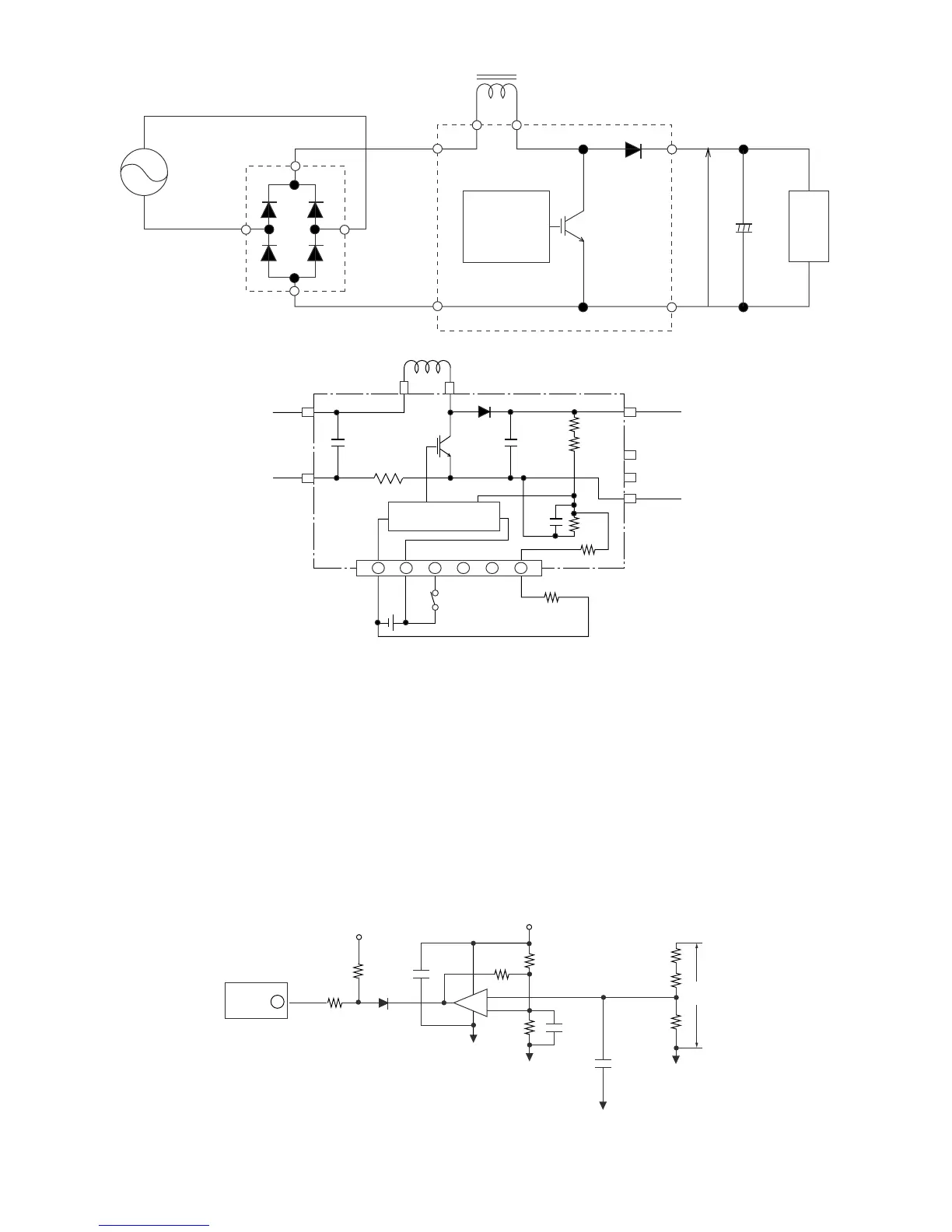
3. Active Filter Driving Electronics Circuit
At the operation of compressor, the microcomputer (IC1), as the 50th pin gets “H”, will turn the transistor Q4 ON through the transistor Q3. By this,
18V is supplied to the 3rd pin of connector BCN13 of the Active Filter and the Active Filter will be turned ON.
4. Protection Circuit of Active Filter
In order to prevent from the destruction of Active Filter due to the excessive over output voltage of Active Filter, the Active Filter will be turned OFF
immediately at the abnormal output voltage by monitoring the output voltage. At the same time, the operation of compressor will be stopped. Detec-
tion circuit of the abnormal voltage detects the abnormal voltage by inputting the output voltage of Active Filter to the 4th pin of comparator IC (IC5) at
the divided voltage by the resistors (R31, R32 and R33) and comparing with reference voltage. When the output voltage of Active Filter reaches 450V
or higher, the 4th pin of IC5 will be higher than the reference voltage at the 5th pin, the output of comparator will be reversed (HL), the L signal will
be entered at the 52nd. pin of microcomputer (IC1) and the operation of the Active Filter will be stopped.
 Loading...