SHARP(CHINA)INVESTMENT CO.,LTD
0E yalpsiD motpmys melborP E5
tluaf noitacinummoc roodtuo / roodnI esuaC
noitcA sisongaid fo tnetnoC .oN noitcnuflaM
1. Check if the indoor and outdoor connections are
correct. The terminal L and N shall correspond to
each other on indoor and outdoor units. Measure
the voltage on outdoor terminal L and N (before
display of E0 fault). If the voltage is “0”:
Replace the indoor main PCB.
2. If the L & N voltage is normal, measure the
voltage between the outdoor terminal N and 1. If
the voltage change occurs between 0~24V
(change pulse voltage)
Replace the indoor main PCB.
3. If the L & N voltage is normal, measure the
voltage between the outdoor terminal N and 1. If
the voltage change occurs between 0~12V change
pulse voltage), but there is no 24V:
Replace the outdoor power source board.
4. If the L & N voltage is normal, measure the
voltage between the outdoor terminal N and 1. If
the voltage has no change:
Firstly replace the indoor main PCB. If the fault remains
unsolved, replace the outdoor power source board.
1) The indicator is dark: Check IPM
board – Test the pins of rectifier
bridge, fast recovery diode (FRD)
and IGBT elements for any
breakdown, short circuiting or
damage.
2) If no damage, test the DC voltage
between DC+ and DC-. If the voltage
is approx. 310V:
Replace the power source board.
5.
Indicator
on
outdoor
power
source
board
3) If no damage, test the DC voltage
between DC+ and DC-. If the voltage
is zero:
6. If the problem cannot be solved by using the
methods above:
Firstly replace the intelligent power module . If the
problem remains unsolved, replace the indoor main PCB.
Power source board . power factor correction.
1 Energize
and
observe for
approx. 10
minutes. If
E0 is still
displayed or
changed to
E5 after a
period of
time:
7. If this fault appears at the initial installation and
testing of the complete unit
please check if the indoor control board and outdoor
inverter module are of the same generation.
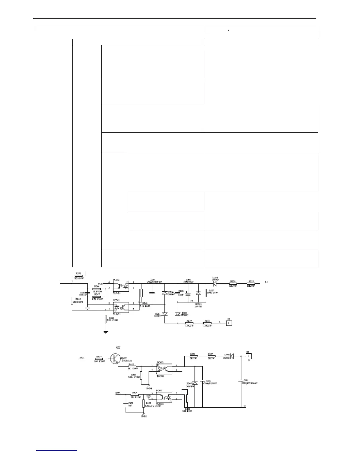
The schematic diagram of Indoor unit communication loop
The schematic diagram of the partial outdoor unit communication loop
3-16
Replace the power source board.
Replace the power source board.
 Loading...