CD-C472/C3400/C3400C/C3800/C3800C
– 12 –
MECHANISM SECTION
• Driving Force Check
Torque Meter Specified Value
Play: TW-2412 Tape 1: Over 80 g
Tape 2: Over 80 g
• Torque Check
Torque Meter
Tape 2
Play: TW-2111 30 to 60 g. cm 30 to 60 g.cm
Fast forward: TW-2231 — 60 to 120 g.cm
Rewind: TW-2231 — 60 to 120 g.cm
Specified
Value
Adjusting
Point
Instrument
Connection
Test Tape
Normal MTT-111 Volume in 3,000 ± Speaker
speed motor. 30 Hz terminal
(MM1) (Load
resistance:
8 ohms)
ADJUSTMENT
Specified Value
Tape 1
• Tape Speed
• AM IF/RF
Signal generator: 400 Hz, 30%, AM modulated
*1. Input: Antenna, Output: TP302
*2. Input: Antenna, Output: TP301
TUNER SECTION
fL: Low-range frequency
fH: High-renge frequency
IF 450 kHz 1,720 kHz T351 *1
Band — 530 kHz (fL): T302 *2
Coverage 1.1 ± 0.1 V
Tracking 990 kHz 990 kHz (fL): T302 *1
Test Stage Frequency Frequency
Display
Setting/
Adjusting
Parts
Instrument
Connection
*1. Input: Antenna, Output: TP301
*2. Input: Antenna, Output: Speaker terminal
• FM RF
Signal generator: 1 kHz, 75 kHz dev., FM modulated
Band — 87.50 MHz L303(fL): *1
Coverage 3.4 V ± 50 mV
RF 98.00 MHz 98.00 MHz L302 *2
(10-30 dB)
Test Stage
Instrument
Connection
Frequency
Frequency
Display
Serring/
Adjusting
Point
• Detection
Signal generator: 10.7 MHz, FM sweep generator
Detection 10.7 MHz 98.00 MHz T352 Input: Pin 1 of
IC303
Output: TP302
IF 10.7 MHz 98.00 MHz T301(Turn Input: Pin 1 of
the core of IC301
transformer Output: TP302
T352 fully
counter-
clookwise.)
Instrument
Connection
Test
Stage
Adjusting
Parts
Frequency
Display
Frequency
Adjusting
Parts
Instrument
Connection
Frequency
Display
Frequency
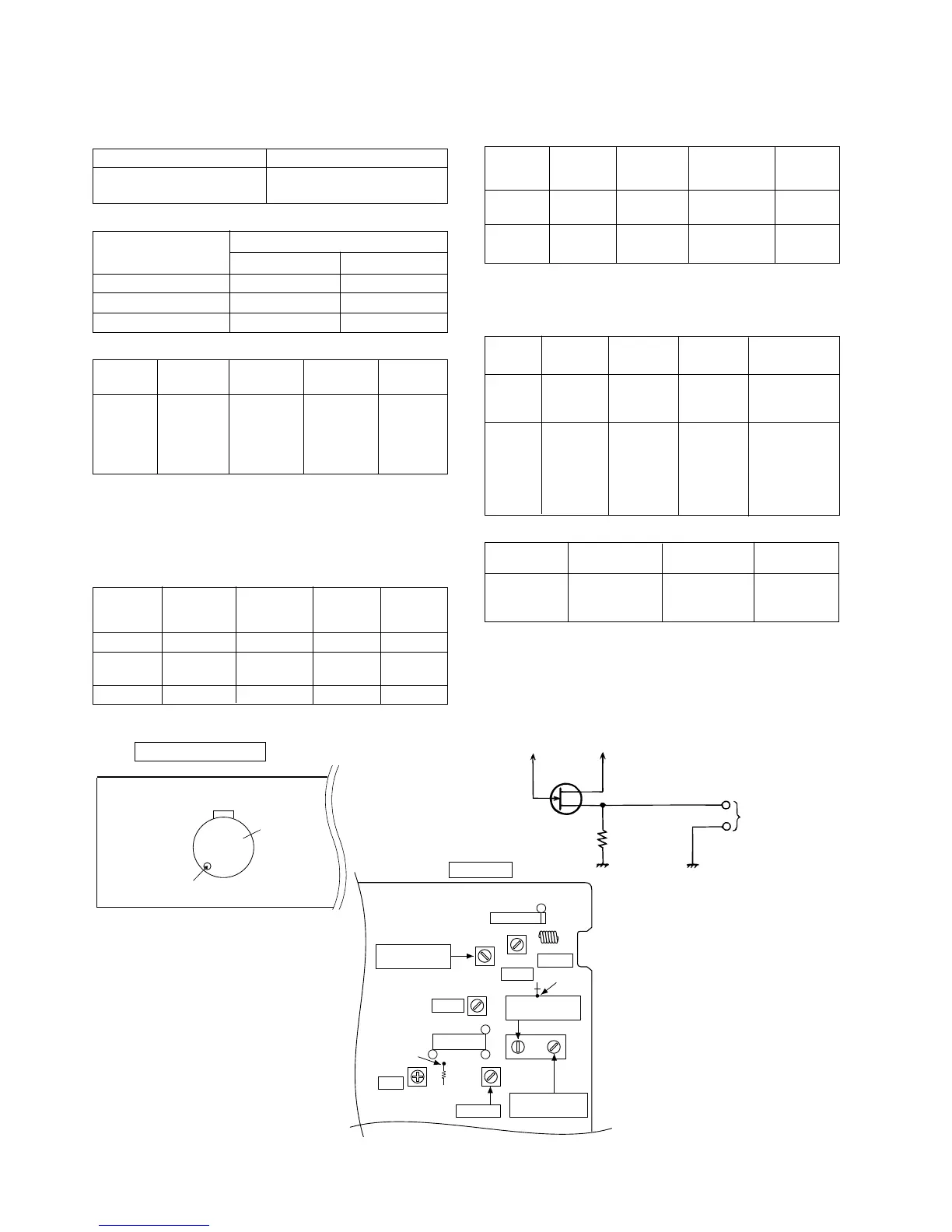
• VCO Frequency
* Adjust for 76 kHz ± 200 Hz.
Notes:
After preparing the test circuit shown in Fig 12-2, connect the
Pin 13 , Pin 21 and ground of the IC303 with test circuit, and
measure the Value.
At this time, apply a standard unmodulated signal input and
adjust the VCO.
Pin 13 of IC303
Pin 21 of IC303
D
G
S
10 kΩ
TO FREQUENCY
COUNTER
FET : 2SK19 or 2SK54
Figure 12-2
TAPE MECHANISM
MM 1
Motor
Volume in motor
98.00 MHz 98.00 MHz VR351* Pin 13, Pin 21
(60 dB) and ground
of IC303
Figure 12-1 ADJUSTMENT POINTS
IC301
IC303
MAIN PWB
13
1
1
21
FM BAND
COVERAGE fL
T301
R316
L303
TP301
L302
T351
T352
TP302
R340
T302
VR351
VCO
AM IF
FM RF
FM DET
FM IF
AM TRACKING
fL
AM BAND
COVERAGE fL
 Loading...