28
LC-13B4E
LC-15B4E
VOLTAGE MEASUREMENT CONDITION:
1. The voltages at test points are measured on
exclusive AC adaptor and the stable supply voltage
of AC 120V. Signals are fed by a color bar signal
generator for servicing purpose and the above
voltages are measured with a 20k ohm/V tester.
INDICATION OF RESISTOR & CAPACI-
TOR:
RESISTOR
1. The unit of resistance “Ω” is omitted.
(K=kΩ=1000 Ω, M=MΩ).
2. All resistors are ± 5%, unless otherwise noted.
(J= ± 5%, F= ± 1%, D= ± 0.5%)
3. All resistors are 1/16W, unless otherwise noted.
4. All resistors are Carbon type, unless otherwise
noted.
C
: Solid
W
: Cement
S
: Oxide Film
T
: Special
N
: Metal Coating
CAPACITOR
1. All capacitors are µF, unless otherwise noted.
(P=pF=µµF).
2. All capacitors are 50V, unless otherwise noted.
3. All capacitors are Ceramic type, unless otherwise
noted.
(ML): Mylar (TA): Tantalum
(PF): Polypro Film (ST): Styrol
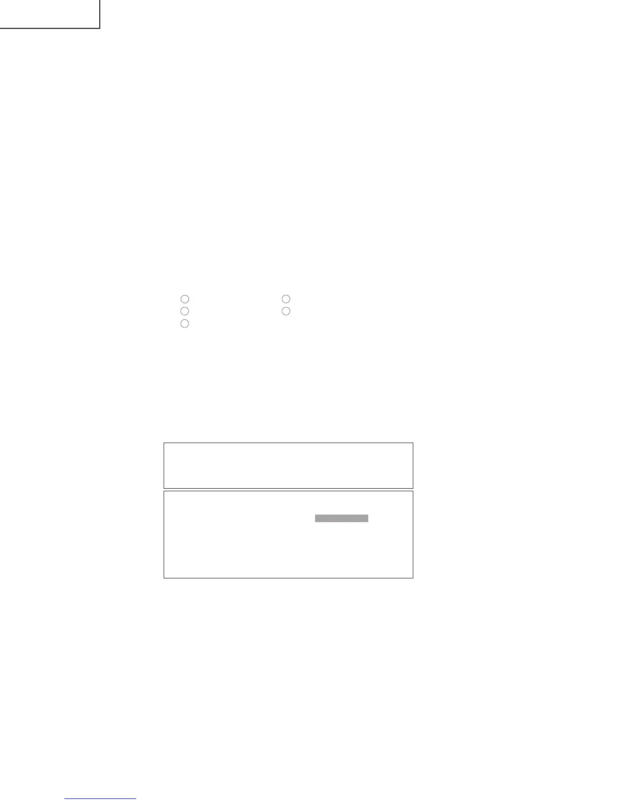
CAUTION:
This circuit diagram is original one, therefore there may be a
slight difference from yours.
IMPORTANT SAFETY NOTICE:
PARTS MARKED WITH “
å
” ( ) ARE
IMPORTANT FOR MAINTAINING THE SAFETY OF
THE SET. BE SURE TO REPLACE THESE PARTS
WITH SPECIFIED ONES FOR MAINTAINING THE
SAFETY AND PERFORMANCE OF THE SET.
DESCRIPTION OF SCHEMATIC DIAGRAM
 Loading...