R-210D
16
Pin No. Signal I/O Description
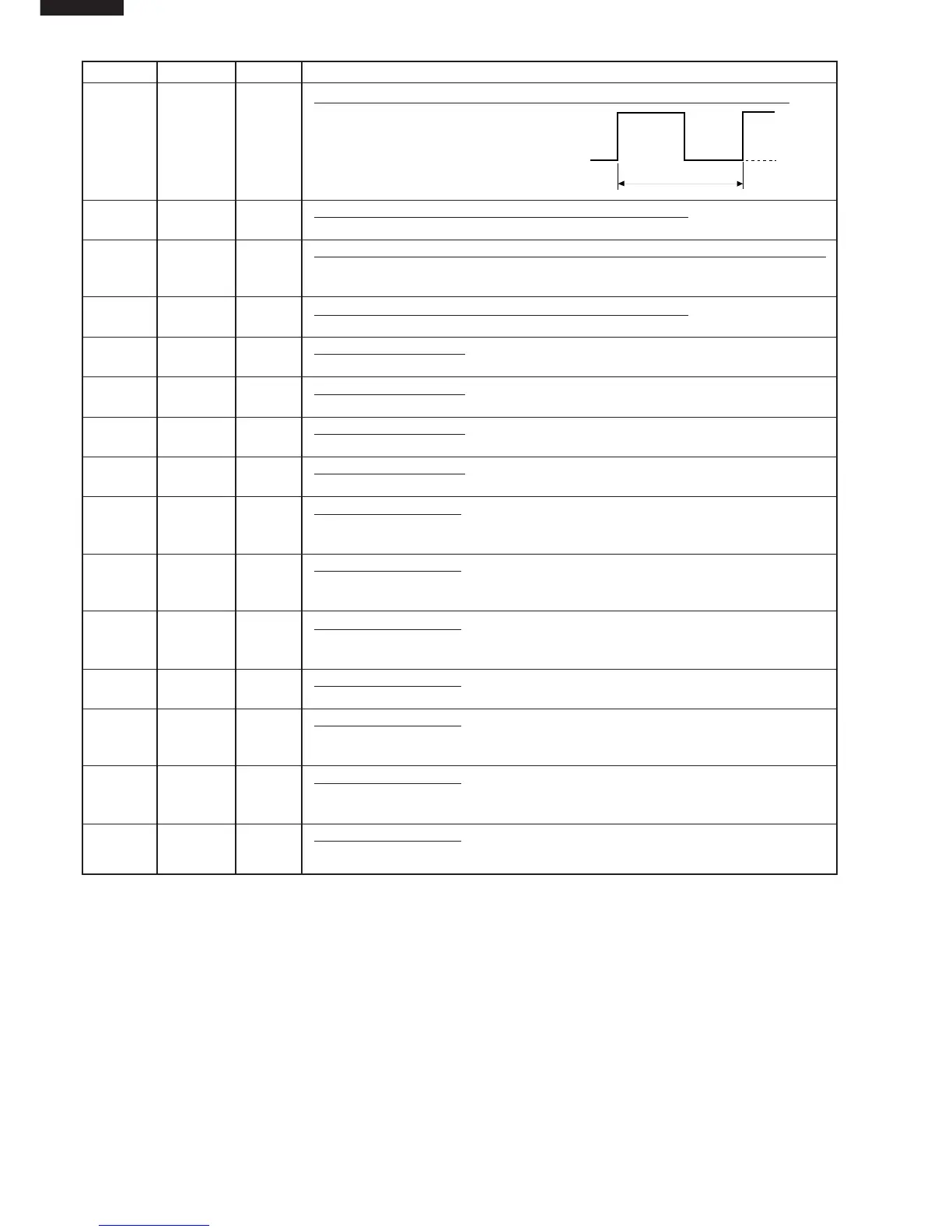
17 INT1 IN Signal to synchronize LSI with commercial power source frequency.
This is basic timing for all real time process-
ing of LSI.
18-19 AIN0-AIN1 IN Terminal to change functions according to the model.
Signal in accordance with the model in operation is applied to set up its function.
20 AIN2 IN Input signal which communicates the door open/close information to LSI.
Door closed; "H" level signal.
Door opened; "L" level signal.
21 AIN3 IN Terminal to change functions according to the model.
Signal in accordance with the model in operation is applied to set up its function.
22 P00 OUT Digit selection signal.
Signal is input to the anodes of the light-emitting diodes (LD30 - LD34).
23 P01 OUT Digit selection signal.
Signal is input to the anodes of the light-emitting diodes (LD9 - LD16).
24 P02 OUT Digit selection signal.
Signal is input to the anodes of the light-emitting diodes (LD17 - LD24).
25 P03 OUT Digit selection signal.
Signal is input to the anodes of the light-emitting diodes (LD1 - LD8).
26 P10 OUT Segment data signal.
Signal is input to the cathodes of the light-emitting diodes (LD1, LD9, LD17 and
LD30).
27 P11 OUT Segment data signal.
Signal is input to the cathodes of the light-emitting diodes (LD2, LD10, LD18 and
LD31).
28 P12 OUT Segment data signal.
Signal is input to the cathodes of the light-emitting diodes (LD3, LD11, LD19 and
LD32).
29 P13 OUT Segment data signal.
Signal is input to the cathodes of the light-emitting diodes (LD4, LD12 and LD20).
30 D0 OUT Segment data signal.
Signal is input to the cathodes of the light-emitting diodes (LD5, LD13, LD21 and
LD33).
31 D1 OUT Segment data signal.
Signal is input to the cathodes of the light-emitting diodes (LD6, LD14, LD22 and
LD34).
32 D2 OUT Segment data signal.
Signal is input to the cathodes of the light-emitting diodes (LD7, LD15 and LD23).
20 msec
H : GND
L (-5V)
 Loading...