GB-3
4
1
5
2
10
3
679
11
12
13
8
17
16
15
14
18
19
POWER
%
ON
1
2
3
4
5
6
7
8
9
/ 100%
/ 50%
/ 20%
/ 10%
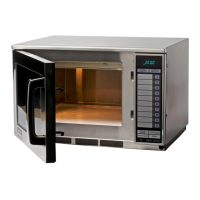
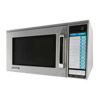
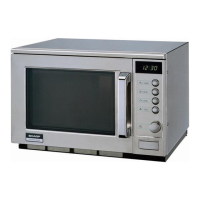
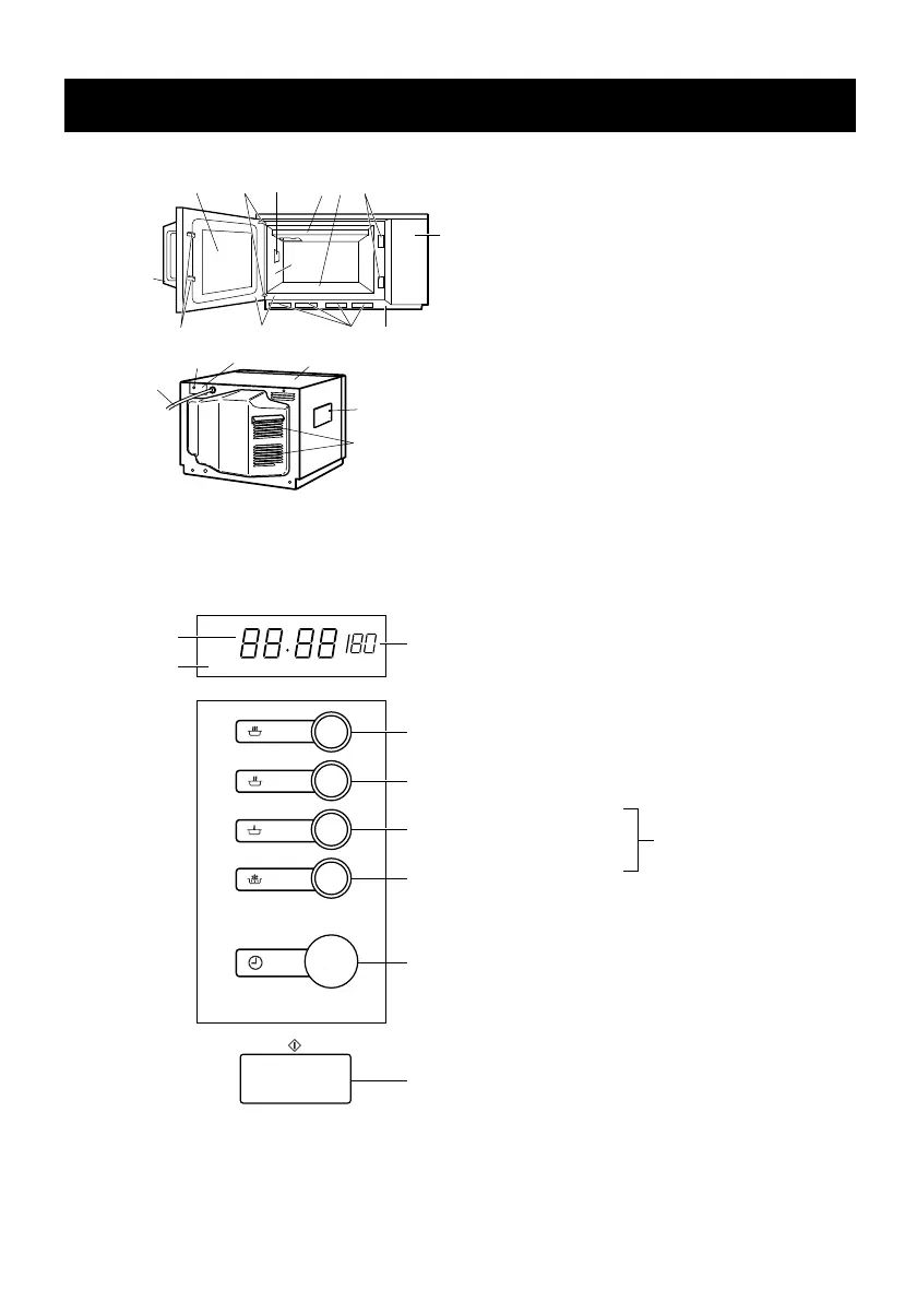
PART NAMES
OVEN
CONTROL PANEL
1 Control panel
2 Door lock openings
3 Ceramic fl oor
4 Splash cover
5 Oven lamp
6 Air intake fi lter
7 Air intake opening
8 Oven cavity
9 Door seals and sealing surfaces
10 Door hinges
11 Door
12 Safety door latches
13 Door open handle
14 Outer cabinet
15 Oven lamp access cover
16 Ventilation openings
17 Power supply cord
18 Mounting plate
19 Screw for mounting plate
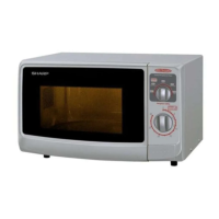
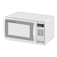
DISPLAY AND INDICATORS
Check indicators after the oven starts to confi rm
the oven is operating as desired.
1 Cook indicator
This indicator shows cooking in prog-
ress.
2 Digital display
3 Microwave power level indicator
OPERATING BUTTONS
4 Power 100%
5 Power 50%
6 Power 20%
7 Power 10%
8 ELECTRONIC TIMER
Rotate the knob to enter cooking time.
9 START button
MICROWAVE
POWER LEVEL
button
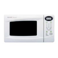
* The illustration of OPERATING BUTTONS is for
R- 22AM/R- 23AM.
Although the design for R- 25AM is slightly
different,each button name and the function is
same.
R23AM_OM_NORDIC_5_GB_SE_NO_FI_DK3 3R23AM_OM_NORDIC_5_GB_SE_NO_FI_DK3 3 2013-12-02 11:12:532013-12-02 11:12:53
 Loading...