EasyManua.ls Logo

Sharp R-230HW User Manual

Sharp R-230HW
36 pages
To Next Page IconTo Next Page
To Previous Page IconTo Previous Page
Page #9 background image
7
R-203HW
R-220HW
R-230HW
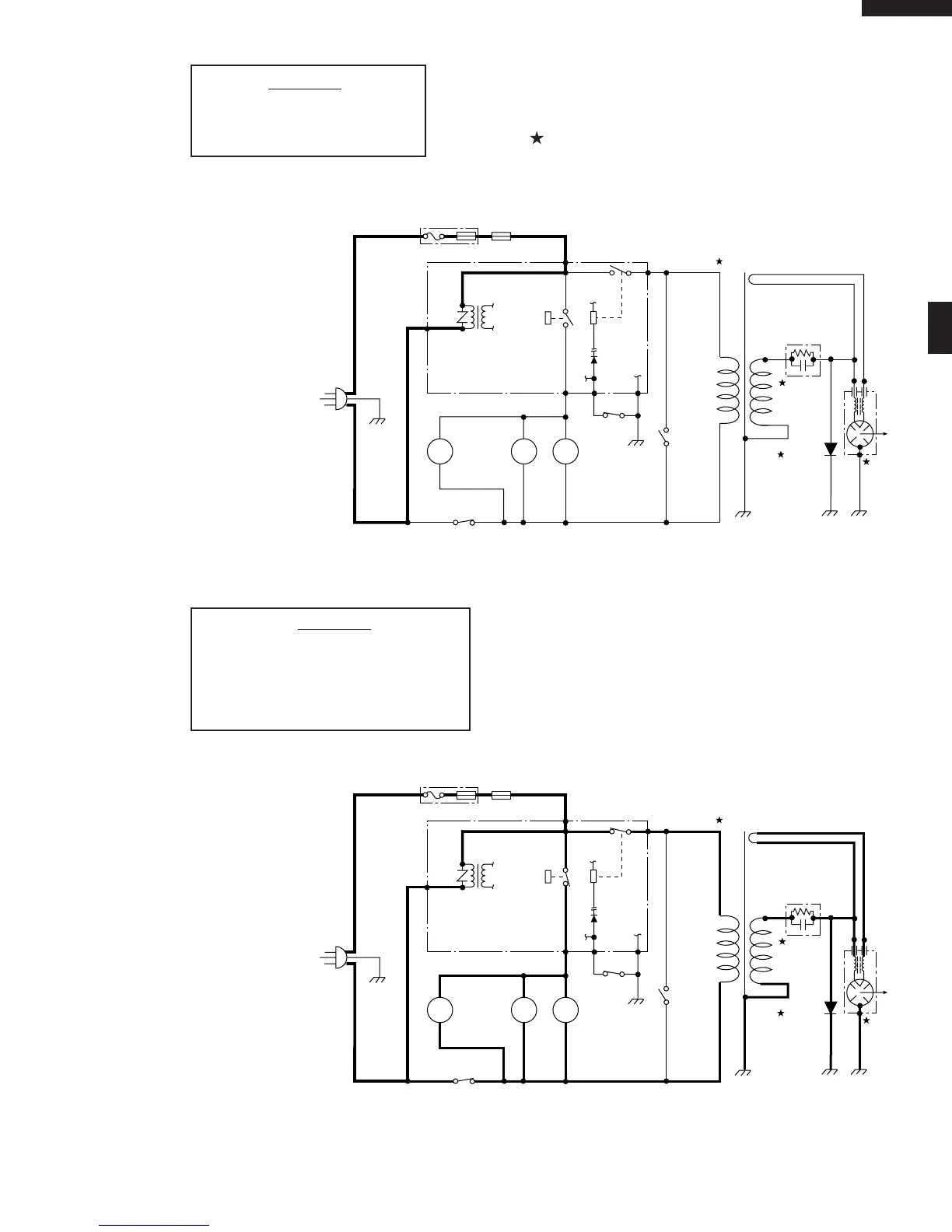
Figure O-1. Oven Schematic-Off Condition
SCHEMATIC
NOTE: CONDITION OF OVEN
1. DOOR CLOSED
2. CLOCK APPEARS ON DISPLAY
SCHEMATIC
NOTE: CONDITION OF OVEN
1. DOOR CLOSED
2. COOKING TIME PROGRAMMED
3. VARIABLE COOKING CONTROL "P-HI"
4. "START" PAD TOUCHED
Figure O-2. Oven Schematic-Cooking Condition
NOTE: " " indicates components with potentials above 250V.
POWER
TRANSFORMER
RECTIFIER
MAGNETRON
CAPACITOR
0.82µF
AC2100V
C/T FUSE
120V AC
60 Hz
OVEN
LAMP
TURN-
TABLE
MOTOR
FAN
MOTOR
MONITOR
SWITCH
SECONDARY
INTERLOCK
SWITCH
TTM
OL FM
GRN
A3
COM.
DOOR
SENSING
SWITCH
B2 B1
(RY-1)
(RY-2)
CONTROL UNIT
PRIMARY
INTERLOCK
RELAY
A1
N.O.
TEMPERATURE
FUSE (OVEN)
POWER
TRANSFORMER
RECTIFIER
CAPACITOR
0.82µF
AC2100V
C/T FUSE
120V AC
60 Hz
OVEN
LAMP
TURN-
TABLE
MOTOR
FAN
MOTOR
MONITOR
SWITCH
SECONDARY
INTERLOCK
SWITCH
TTM
OL FM
GRN
A3
N.O.
COM.
DOOR
SENSING
SWITCH
B2 B1
(RY-1)
(RY-2)
CONTROL UNIT
PRIMARY
INTERLOCK
RELAY
TEMPERATURE
FUSE (OVEN)
A1
MAGNETRON

Questions and Answers:

Sharp R-230HW Specifications

General IconGeneral
BrandSharp
ModelR-230HW
CategoryMicrowave Oven
LanguageEnglish

Summary

Precautions for Microwave Exposure Safety

Before Servicing Procedures

Service Personnel Warnings

Pre-Servicing Safety Steps

Steps to take before servicing the oven, including disconnecting power and discharging capacitors.

Microwave Measurement Procedure

Leakage Test Execution

Procedure for performing the closed-door microwave leakage test.

Foreword and Introduction

General Operating Warnings

Essential conditions and checks before operating or servicing the oven.

High Voltage Danger Warnings

Identifies high-voltage parts that pose a severe shock hazard during servicing.

Operation Sequence and Power Levels

Component Descriptions and Functions

Troubleshooting Guide

Troubleshooting Blown C/T Fuse

Specific checks and replacements required when the C/T fuse blows.

Troubleshooting Safety and Procedures

General safety precautions and procedures for performing troubleshooting.

Test Procedures Overview

Magnetron Assembly Test

Procedure for testing the magnetron assembly for proper operation.

Component Testing Procedures

Microwave Output Power Test

Procedure for measuring microwave power output using a water temperature rise test.

Power Transformer Test

Procedure for testing the power transformer resistance and continuity.

Component Testing Procedures (Continued)

High Voltage Rectifier Test

Procedure for testing the high voltage rectifier assembly.

Primary Interlock System Tests

Tests for door sensing switch and primary interlock relay operation.

Blown C/T Fuse Test

Procedure to test for a blown C/T fuse and related safety switches.

High Voltage Capacitor Test

Procedure for testing the high voltage capacitor for shorts or opens.

Touch Control Panel Test

Procedure for testing the touch control panel assembly.

Touch Control Panel Assembly Details

Servicing Procedures and Precautions

Handling Electronic Components

Precautions for handling CMOS LSI and preventing static damage.

Touch Control Panel Servicing

Procedures and precautions for servicing the touch control panel.

Component Replacement and Adjustment

High Voltage Warnings for Servicing

Critical warnings about high voltage hazards during component replacement.

Microwave Energy Exposure Precautions

Precautions to avoid microwave energy exposure before operating the oven.

Wiring Safety Precautions

Essential precautions to prevent electric shock when working with wiring.

Component Replacement and Adjustment (Continued)

Magnetron Removal

Procedure for removing the magnetron from the oven.

Control Panel Assembly Removal

Cooling Fan Motor Removal

Door Switches and Monitor Switch Removal

Door Replacement Procedure

Ordering Replacement Parts

Related product manuals