18
R-305HK
R-305HW
DESCRIPTION OF LSI
LSI
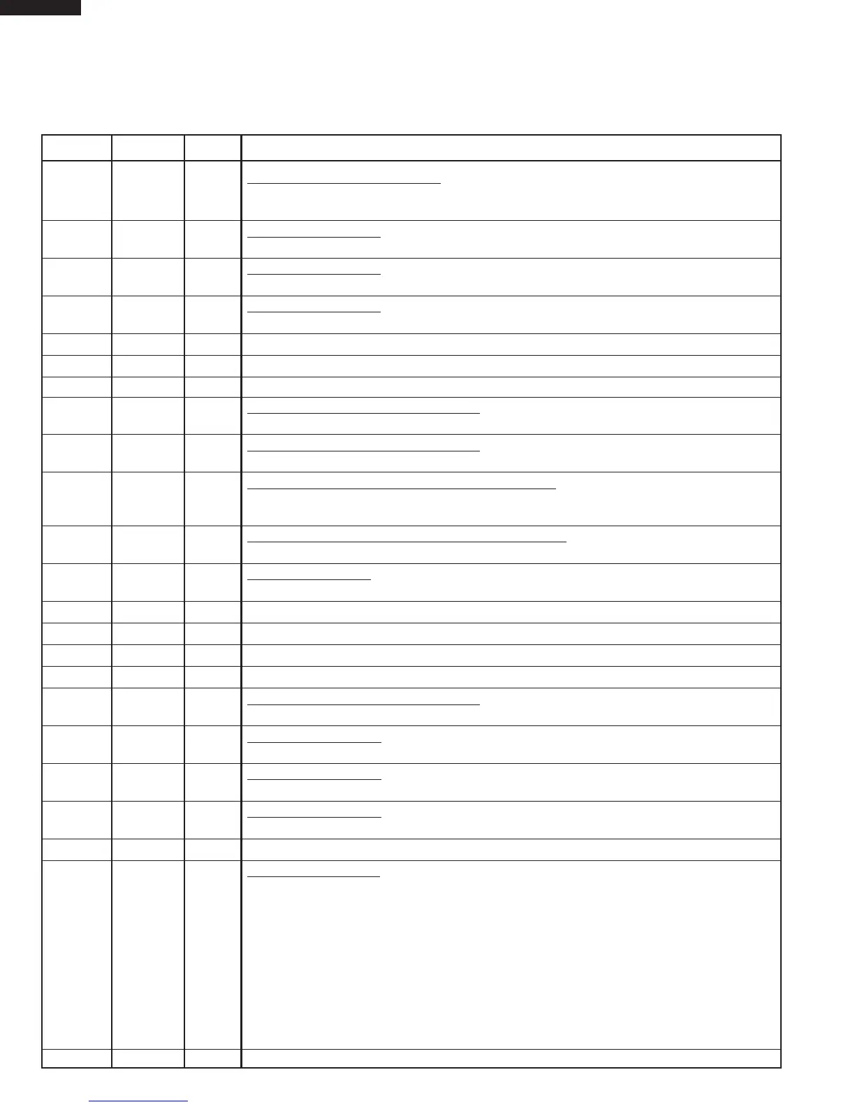
The I/O signal of the LSI is detailed in the following table.
Pin No. Signal I/O Description
1 P50 IN Signal coming from touch key.
When either G9 line on key matrix is touched, a corresponding signal out of P22 - P26 and P31
- P33 will be input into P50. When no key is touched, the signal is held at “H” level.
2 P51 IN Signal similar to P50.
When either G10 line on key matrix is touched, a corresponding signal will be input into P51.
3 P52 IN Signal similar to P50.
When either G11 line on key matrix is touched, a corresponding signal will be input into P52.
4 P53 IN
Signal similar to P50.
When either G12 line on key matrix is touched, a corresponding signal will be input into P53.
5ICINConnected to VSS.
6XT1 IN Connected to VSS.
7XT2
_
Terminal not used.
8 VDD IN
Power source voltage input terminal.
The power souce voltage to drive the LSI. Connected to GND.
9 VSS IN
Power source voltage input terminal.
The power souce voltage to drive the LSI.
10 X1 IN
Internal clock oscillation frequency input setting.
The internal clock frequency is set by inserting the resistor-capacitor oscillation circuit with
respect to X2 terminal.
11 X2 OUT
Internal clock oscillation frequency control output.
Output to control oscillation input of X1.
12 RESET IN
Auto clear terminal.
Signal is input to reset the LSI to the initial state when power is applied.
13-15 P00-P02 OUT Terminal not used.
16 P03 OUT Back light circuit (Light emitting diodes) driving signal.
17 CAPH
_
Terminal not used.
18 CAPL
_
Terminal not used.
19-21
VLC0-VLC2 IN Power source voltage input terminal.
Standard voltage for LCD.
22 COM0 OUT
Common data signal.
Connected to LCD signal COM1.
23 COM1 OUT
Common data signal.
Connected to LCD signal COM2.
24 COM2 OUT
Common data signal.
Connected to LCD signal COM3.
25 COM3 OUT Terminal not used.
26-39
SEG0-SEG13
OUT Segment data signal.
Connected to LCD.
The relation between signals are as follows:
LSI signal (Pin No.) LCD (segment) LSI signal (Pin No.) LCD (segment)
SEG 0 (26)
...................................
SEG 1 SEG 7 (33)
................................
SEG 8
SEG 1 (27)
...................................
SEG 2 SEG 8 (34)
................................
SEG 9
SEG 2 (28)
...................................
SEG 3 SEG 9 (35)
..............................
SEG 10
SEG 3 (29)
...................................
SEG 4 SEG 10 (36)
..............................
SEG 11
SEG 4 (30)
...................................
SEG 5 SEG 11 (37)
..............................
SEG 12
SEG 5 (31)
...................................
SEG 6 SEG 12 (38)
..............................
SEG 13
SEG 6 (32)
...................................
SEG 7 SEG 13 (39)
..............................
SEG 14
40 SEG14 OUT Terminal not used.
 Loading...