R-308JK
R-308JS
R-308JW
R-309JW
24
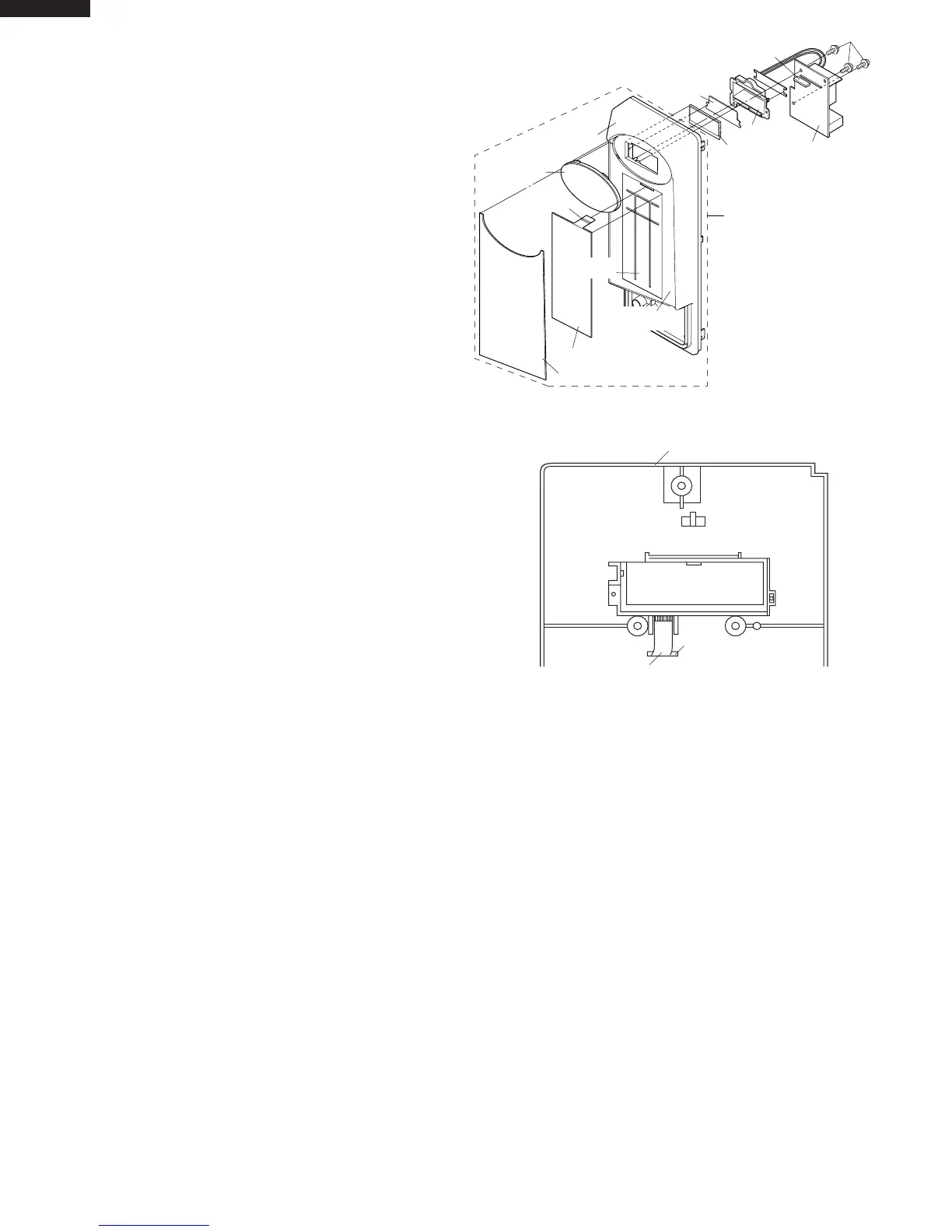
switch to the small depression on the surface of the control
panel frame.
5. Attach the membrane switch to the control panel frame by
rubbing with a soft cloth not to scratch.
6. Tear the backing paper from the new graphic sheet.
7. Adjust the upper edge and left edge of the graphic sheet to
the large depression on the surface of the control panel
frame.
8. Attach the graphic sheet to the control panel frame by
rubbing with a soft cloth not to scratch.
9. Make sure that the liquid crystal display and the LED sheet
are installed in position.
10.Tear the small backing paper from the ribbon cable of the
membrane switch.
11.Attach the ribbon cable to the control panel frame rear side.
12.Place the edge of the membrane switch’s ribbon cable on
the lower portion of the liquid crystal display.
13. Reinstall the LCD holder to the control panel frame.
14.Insert the rubber connector into the long slit of the LCD
holder.
15.Reinstall the control unit to the control panel frame with the
three (3) screws.
NOTE:
Do not contact the contact surface of the ribbon cable
(edge) and the rubber connector directly with your fingers.
This is to avoid oxidized. If display digits are missing or
scrambled, remove control unit and clean contact surface
with alcohol. After cleaning, do not attach the rubber
connector until alcohol dries up. Do not use alcohol or
solution to clean the rubber connector. Make sure that
there is no trash or foreign substance on contact surface
of the rubber connector.
Display window
Small backing
paper
Graphic sheet
Membrame switch
Panel sub assembly
Control panel
frame
Control unit
Large
depression
Small
depression
Liquid
crystal display
LED sheet
LCD holder
Screws
Rubber connector
Figure C-2a. Graphic Sheet and Membrane Switch
Replacement
Slit
Ribbon cable of membrane switch
Control panel frame
Figure C-2b. Rebbon Cable of Membrane Switch
1. Disconnect the power supply cord.
2. Remove turntable and turntable support from oven cavity.
3. Lay the oven on it's backside. Remove the turntable motor
cover by snipping off the material in four corners.
4. Where the corners have been snipped off bend corner
areas flat. No sharp edges must be evident after removal of
the turntable motor cover.
TURNTABLE MOTOR REMOVAL
5. Disconnect wire leads from turntable motor.
(See "Positive lock connector removal")
6. Remove one (1) screw holding turntable motor to oven
cavity.
7. Now the turntable motor is free.
8. After replacement use the one (1) screw to fit the turntable
motor cover.
REMOVAL
1. Disconnect the power supply cord and then remove outer
case.
2. Open the door and block it open.
3. Discharge high voltage capacitor.
4. Disconnect the wire leads from the fan motor.
5. Remove the two (2) screws holding the fan motor to the
oven cavity back plate.
6. Remove the fan blade from the fan motor shaft according to
the following procedure.
7. Hold the edge of the rotor of the fan motor by using a pair
of groove joint pliers.
CAUTION:
* Make sure that no metal pieces enter the gap between
COOLING FAN MOTOR REMOVAL
the rotor and the stator of the fan motor because the
rotor is easily shaven by pliers and metal pieces may be
produced.
* Do not touch the pliers to the coil of the fan motor
because the coil may be cut or injured.
* Do not disfigure the bracket by touching with the pliers.
8. Remove the fan blade from the shaft of the fan motor by
pulling and rotating the fan blade with your hand.
9. Now, the fan blade will be free.
CAUTION:
* Do not reuse the removed fan blade because the hole
(for shaft) may be larger than normal.
10.Now, the fan motor is free.
 Loading...