18
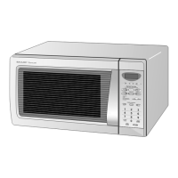
R-308DW
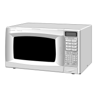
R-310DK
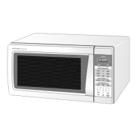
R-310DW
1-2 VL2-VL1 IN Power source voltage input terminal.
Standard voltage for LCD.
3-6 AN7-AN4 IN Terminal to change cooking input according to the Model.
By using the A/D converter contained in the LSI, DC voltage in accordance with the Model
in operation is applied to set up its cooking constant.
7 P63 OUT Terminal not used.
8 AN2 IN Input terminal to judge the model.
Connected to GND through the pull-down resistor R78.
9 AN1 IN To input signal which communicates the door open/close information to LSI.
Door close "H" level signal (0V). Door open "L" level signal (-5V).
10 AN0 IN Input terminal to judge the model.
The signal out of P20 will be input into AN0 through G1 line on key matrix. The LSI will
judge the model by this signal.
TOUCH CONTROL PANEL ASSEMBLY
OUTLINE OF TOUCH CONTROL PANEL
The The touch control section consists of the following units.
(1) Key Unit
(2) Control Unit (The Control Unit consists of Power Unit and
CPU Unit).
The principal functions of these units and the signals commu-
nicated among them are explained below.
Key Unit
The key unit is composed of a matrix, signals generated in the
LSI are sent to the key unit through P20, P21, P22, P23, P24,
P25, P26 and P27
.
When a key pad is touched, a signal is completed through the
key unit and passed back to the LSI through P41, P43, P44,
P45 and AN0 to perform the function that was requested.
Control Unit
Control unit consists of LSI, ACL circuit, indicator circuit, power
source circuit, relay circuit, buzzer circuit, synchronizing signal
circuit and back light circuit.
1) ACL
This circuit generates a signal which resets the LSI to the
initial state when power is supplied.
2) Indicator Circuit
This circuit consists of 22 segments and 3 common elec-
trodes using a Liquid Crystal Display.
3) Power Source Circuit
This circuit generates voltages necessary in the control unit
from the AC line voltage.
In addition, the synchronizing signal is available in order to
compose a basic standard time in the clock circuit.
Symbol Voltage Application
VC -5V LSI(IC1)
4) Relay Circuit
A circuit to drive the magnetron, fan motor, turntable motor
and light the oven lamp.
5) Buzzer Circuit
The buzzer is responsive to signals from the LSI to emit
audible sounds (key touch sound and completion sound).
6) Synchronizing Signal Circuit
The power source synchronizing signal is available in order
to compose a basic standard time in the clock circuit.
It accompanies a very small error because it works on
commercial frequency.
7) Door Sensing Switch
A switch to “tell” the LSI if the door is open or closed.
8) Back Light Circuit
A circuit to drive the back light (Light emitting diodes LD1-
LD4).
LSI(IXA019DR)
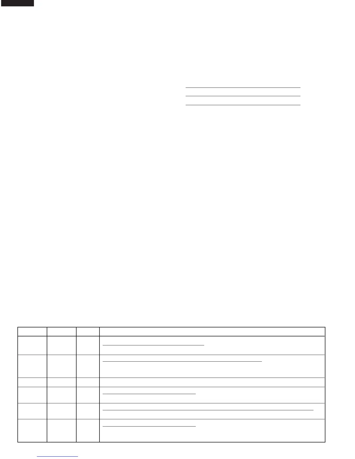
The I/O signal of the LSI(IXA019DR) is detailed in the following table.
Pin No. Signal I/O Description
 Loading...