Do you have a question about the Sharp R-380LS and is the answer not in the manual?
| Wattage | 1000 Watts |
|---|---|
| Power Output | 1000 Watts |
| Cooking Levels | 10 |
| Voltage | 120V |
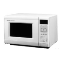
| Type | Countertop |
| Control Type | Touch Control |
Details essential safety guidelines, including earthing, microwave radiation, and operational precautions.
Outlines critical safety protocols, capacitor discharge, and microwave energy avoidance for service technicians.
Explains sequences for high cooking, medium levels, and sensor cooking operations.
Provides a systematic guide to identify problems and check faulty parts based on symptom and condition.
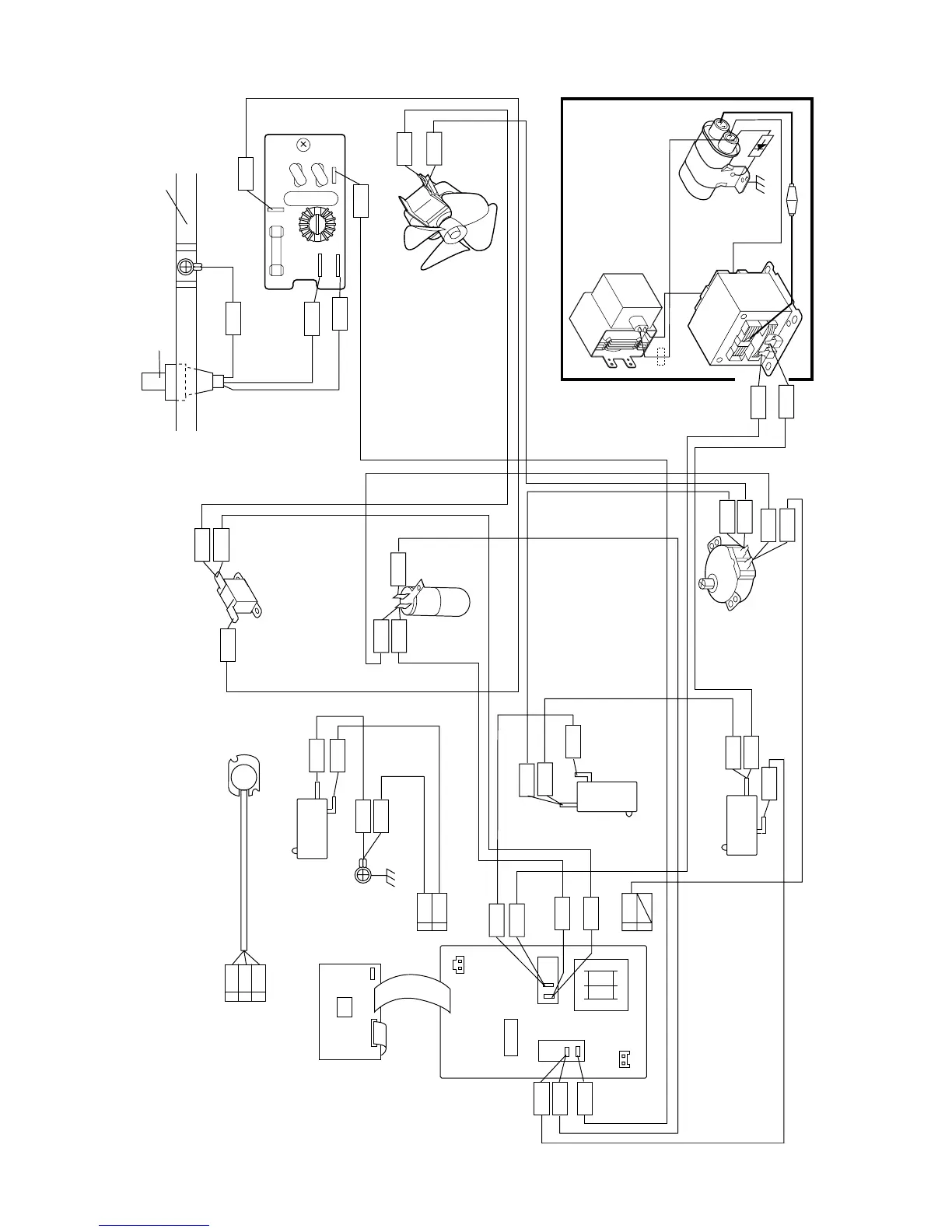
Details test procedures for the magnetron, power transformer, HV rectifier, and capacitor.
Describes tests for relays, PWB foil patterns, and the AH sensor, including control unit interaction.
Lists essential safety checks and warnings to be followed before performing any maintenance.
Provides procedures for removing and replacing HV rectifier, capacitor, fuse, and magnetron.
Details the requirements and preparation for conducting a microwave leakage test.