TEST PROCEDURES
PROCEDURE
LETTER
COMPONENT TEST
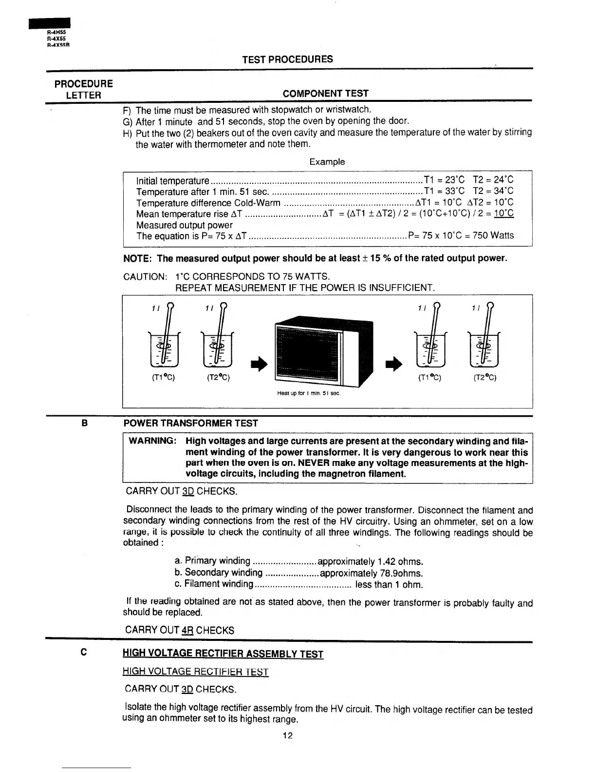
F) The time must be measured with stopwatch or wristwatch.
G) After 1 minute and 51 seconds, stop the oven by opening the door.
H) Put the two (2) beakers out of the oven cavity and measure the temperature of the water by stirring
the water with thermometer and note them.
Example
Initial temperature . .
. . . . . . . . . . . . . . . . . . . . . . . . . . . . . . . . . . . . . . . . . . . . . . . . . . . . . . . . . . . . . . . . . . . . . . . . . . . . . . . . .
Tl = 23°C T2 = 24°C
Temperature after 1 min. 51 sec.
. . . . . . . . . . . . . . . . . . . . . . . . . . . . . . . . . . . . . . . . . . . . . . . . . . . . . . . . . . .
Tl = 33°C T2 = 34°C
Temperature difference Cold-Warm
. . . . . . . . . . . . . . . . . . . . . . . . . . . . . . . . . . . . . . . . . . . . . . . . . . .
AT1 = 10°C AT2 = 10°C
Mean temperature
rise AT . . . . . . . . . . . . . . . . . . . . . . . . . . . . . .
AT = (AT1 rt AT2) / 2 = (1 O”C+lO”C) / 2 = 10°C
Measured output power
The equation is P= 75 x AT . . . . . . . . . . . . . . . . . . . . . . . . . . . . . . . . . . . . . . . . . . . . . . . . . . . . . . . . . . . . . . P= 75 x
10°C = 750 Watts
NOTE: The measured output power should be at least f 15 % of the rated output power.
CAUTION: 1°C CORRESPONDS TO 75 WATTS.
REPEAT MEASUREMENT IF THE POWER IS INSUFFICIENT.
(Tl ‘C)
(T2’C) (Tl ‘C)
Heat up for 1 min. 51 set
II
2 -
- -
- -
- -
(T2’C)
B
POWER TRANSFORMER TEST
WARNING:
High voltages and large currents are present at the secondary winding and fila-
ment winding of the power transformer. It is very dangerous to work near this
part when the oven is on. NEVER make any voltage measurements at the high-
voltage circuits, including the magnetron filament.
CARRY OUT 3D CHECKS.
Disconnect the leads to the primary winding of the power transformer. Disconnect the filament and
secondary winding connections from the rest of the HV circuitry. Using an ohmmeter, set on a low
range, it is possible to check the continuity of all three windings. The following readings should be
obtained :
-_
a. Primary winding
. . . . . . . . . . . . . . . . . . . . . . . . . approximately
1 .42 ohms.
b. Secondary winding
. . . . . . . . . . . . . . . . . . . . . approximately
78.9ohms.
c. Filament winding . . . . . . . . . . . . . . . . . . . . . . . . . . . . . . . . . . . . . .
less than 1 ohm.
lf the reading obtained are not as stated above, then the power transformer is probably faulty and
should be replaced.
CARRY OUT $FJ CHECKS
C
HIGH VOLTAGE RECTIFIER ASSEMBLY TEST
HIGH VOLTAGE RECTIFIER TEST
CARRY OUT 3D CHECKS.
Isolate the high voltage rectifier assembly from the HV circuit. The high voltage rectifier can be tested
using an ohmmeter set to its highest range.
12
 Loading...