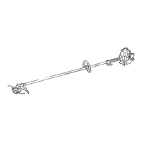
Mainshaft
Powerhead
Outer Tube
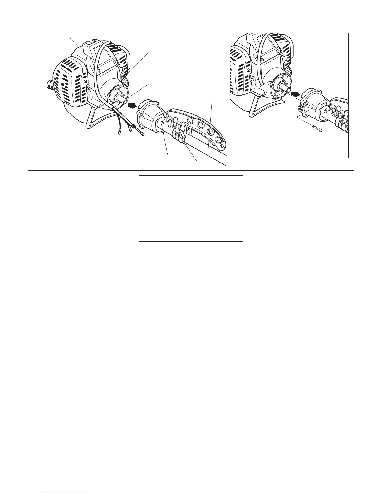
Figure 5
Fan Cover Housing
Swivel Lock
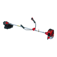
The B450 is equipped with a swivel feature that allows
the outer tube (and cutting attachment) to be rotated
without rotating the powerhead. Tightening the swivel
lock prevents outer tube rotation.
Figure 5A
Swivel Grease
Plug
Install Mainshaft and Outer Tube
1. Place the powerhead on a flat surface,
resting on its stand.
2. Lubricate the mainshaft splines with mo
-
lybdenum disulfide (moly) type grease.
3. Slide the outer tube/cap assembly on to
the fan cover. Make sure the mainshaft
splines are fully engaged into the clutch
drum. See Figure 5.
CAUTION!
Do not force the outer tube into the
powerhead! Forcing the outer tube
into the powerhead may damage the
splines on the mainshaft and/or clutch
drum shaft. If installation proves diffi-
cult, rotate the powerhead or mainshaft
until you feel the mainshaft splines
engage into the clutch drum.
4. If necessary, rotate the outer tube as
-
sembly until the gearcase output shaft
is pointing down, opposite to the spark
plug.
5. Install four screws with cable holder in
upper right mounting position as shown
in Figure 5A. Tighten all screws evenly
to 26-44 in/lbs.
6. Test swivel operation by rotating outer
tube. If necessary loosen the swivel lock
wing nut.
 Loading...