8014640/YWI5/2016-08-08 • Subject to change without notice • SICK AG • Waldkirch • Germany • www.sick.com 4LECTOR62X | SICK
Setup and function
NOTE
Risk of damaging the swivel connector
The plug unit may be moved up to 180° from end
point to end point of the stop. The ECO variant has
no swivel connector.
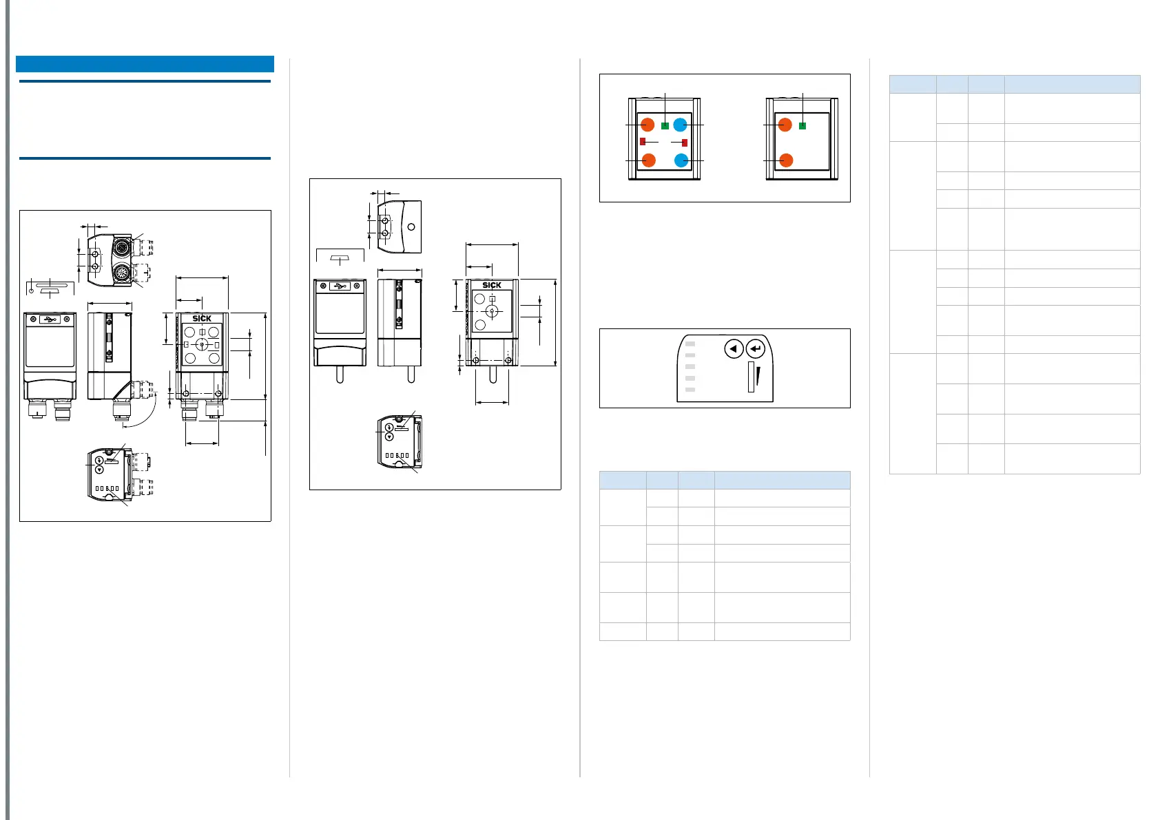
Device structure Lector620 with swivel
connector
Ready
Read Diagn
Result
TeachIn
LED
Auto-Setup
Data
Autofocus
LNK TX
Userdefined
300
200
100
70
40
100
0
[mm]
[%]
1
2
3
5
a
4
1
6
7
8
9
ß
á
à
26.5
35.6
10
4.8
21.5
26
43
71
17.44
Ø 10
All dimensions in mm
Fig. 6: Structure of Lector620 Professional, High Speed,
DPM Plus and OCR
1. M5 blind tapped holes, 5 mm deep (4 x), for mounting
the Lector620
2. “Ethernet” connection (4-pin M12 female connector,
D-coded)
3. “Power/Serial Data/CAN/I/O” connection (17-pin. M12
male connector, A-coded)
4. M5 sliding nuts, 5 mm deep (2 x), for mounting the
Lector620 (alternative)
5. Swivel connector
6. Reading window
7. Function button (2 x)
8. Bar graph display
9. RGB LEDs for status indication (2 modes), 5 x
ß Cover(ap)
à USB port, 5-pin female connector, Micro B type
á Slot for microSD memory card
â LED for microSD memory card
Device structure ICR620D-T51503
(part number 1064256)
See downloadable dimensional drawing on the SICK
product page in the web. Path:
www.sick.com/lector62x > Select device > Tab “Tech-
nical data” > Section “Technical drawings”
Device structure Lector620 with cable outlet
Ready
Read Diagn
Result
TeachIn
LED
Auto-Setup
Data
Autofocus
LNK TX
Userdefined
300
200
100
70
40
100
0
[mm]
[%]
1
2
1
3
4
5
6
8
7
9
26.5
35.6
10
4.8
43
21.5
26
71
Ø 10
All dimensions in mm
Fig. 7: Structure of Lector620 ECO
1. M5 blind tapped holes, 5 mm deep (4 x), for mounting
the Lector620
2. M5 sliding nuts, 5 mm deep (2 x), for mounting the
Lector620 (alternative)
3. Reading window
4. Function button (2 x)
5. Bar graph display
6. RGB LEDs for status indication (2 modes), 5 x
7. Cable (0.9 m) with 15-pin D-Sub HD male connector
(“Power/Serial Data/CAN/I/O”)
8. Cover(ap)
9. USB port, 5-pin female connector, Micro B type
Lighting unit
3
1
1
1
1
Fig. 8: Lighting unit
1. Integrated lighting = 4 x LED (2 x left/2 x right);
ECO variant: 2 x LED (2 x left)
2. Feed-back spot (e.g. for Good Read) = 1 x green LED
3. Aiming laser for alignment, can be deactivated = 2 x red
laser LEDs
The ECO variant has no aiming laser.
Status indicators, functions
Ready
Read Diagn
Result
TeachIn
LED
Auto-Setup
Data
Autofocus
LNK TX
Userdefined
300
200
100
70
40
100
0
[mm]
[%]
O
O
O
O
O
Fig. 9: LED status indicators, function buttons and bar
graph display
Status indicators in read mode
Display LED Color Status
Ready
O
Green Device ready to read
O
Red Hardware or software error
Result
O
Green Read operation successful
O
Red Read operation unsuccessful
LED
O
Green Read mode: Illumination on,
internal reading gate open
Data
O
Yellow Data output via host interface
LNK TX
Ö
Green Data trafc via Ethernet
O = illuminated; Ö = ashing
Tab. 3: Status indicators in read mode
Status indicators in conguration mode
Display LED Color Status
Read
Diagn
O
Blue Test (reading diagnostics)
selected
Ö
Blue Test started
TeachIn
O
Blue Teach-in selected (default:
Match code)
Ö
Blue Teach-in started
O
Green Teach-in successful
O
Red Teach-in unsuccessful
(match code default setting:
unable to teach in any code)
Auto-
Setup
O
Blue Auto-Setup selected
Ö
Blue Auto-Setup started
O
Green Auto-Setup successfully quit
O
Yellow Auto-Setup was partially suc-
cessful
O
Red Auto-Setup was unsuccessful
Auto fo-
cus (not
with
the ECO
variant)
O
Green Function can be dened by
user
O
Yellow Function can be dened by
user
O
Blue Function can be dened by
user
O
Red Function can be dened by
user
O = illuminated; Ö = ashing
Tab. 4: Status indicators in conguration mode
Audible status indicator (beeper)
Signals a selectable event (default: Good Read). User
operations are accompanied by a series of sounds.
Can be switched off
Functions
For information on operation of functions, see
Onlinehelpfordeviceincongurationsoftware
SOPAS ET.
Read Diagn (read diagnosis)
Percentage analysis: The device records a series of
images and uses the current reading performance
settings to decode them. The read rate of the last 10
read operations is displayed in % using the bar graph.