0
0
2
1
3
(0.12)
2
(0.08)
1
(0.04)
7
(0.28)
6
(0.24)
5
(0.2)
4
(0.16)
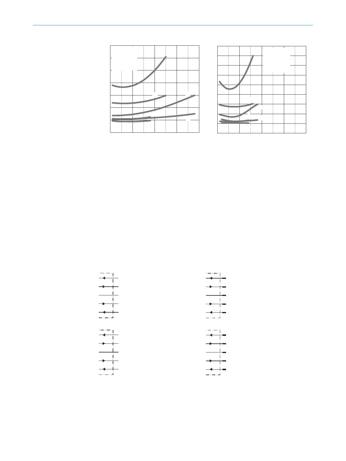
Repeatability in mm (inch)
1,000
(39.37)
2,000
(78.74)
3,000
(118.11)
4,000
(157.48)
Distance in mm (inch)
4
3
6
5
1) -Axx3x: 6 %
2) -Axx3x: 90 %
3) -Axx6x: 6 %
4) -Axx6x: 90 %
5) -Axx4x: 6 %
6) -Axx4x: 90 %
図: H-3
0
0
2
1
3
(0.12)
2
(0.08)
1
(0.04)
7
(0.28)
8
(0.31)
9
(0.35)
6
(0.24)
5
(0.2)
4
(0.16)
Repeatability in mm (inch)
1,000
(39.37)
2,000
(78.74)
3,000
(118.11)
4, 000
(157.48)
Distance in mm (inch)
6
5
4
3
1) -Axx1x: 6 %
2) -Axx1x: 90 %
3) -Axx5x: 6 %
4) -Axx5x: 90 %
5) -Axx2x: 6 %
6) -Axx2x: 90 %
図: H-4
67.2 取付け
適切なブラケットを使用してセンサを取り付けます(SICK 付属品カタログを参
照)。
センサの締め付けトルクの最大許容値 0,8 Nm に注意してください。
センサに対して対象物が検出可能な方向にあることを確認してください。
67.3 電子機器
センサの接続は無電圧 (U
v
= 0 V) で行わなければなりません。接続タイプに応じ
てグラフ [B を参照] の情報に留意してください:
– コネクタ接続: ピン配置
– ケーブル: 芯線の色
+ (L+)
QA
- (M)
brn
wht
blu
Q1
blk
SenderOff
gra
図: B: -A15X3
+ (L+)
QA
- (M)
brn
wht
blu
1
2
3
Q1
blk
4
SenderOff
gra
5
図: B-2: -A25X3/ -A35X3
+ (L+)
QA
- (M)
brn
wht
blu
Q1
blk
L/D
gra
図: B: -A15X7
+ (L+)
QA
- (M)
brn
wht
blu
1
2
3
Q1
blk
4
L/D
gra
5
図: B: -A25X7 / -A35X7
すべての電気機器を接続してから供給電圧 (U
v
> 0 V) を印加、あるいは電源を入れ
てください。センサの緑色の LED 表示が点灯します。
接続図の説明 (グラフ B):
投光器 Off = 投光 LED のスイッチオフ、HIGH active
L/D = ライト/ダークオン
67
コミッショニング
90
8020879.ZM26 | SICK
Subject to change without notice

 Loading...


