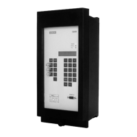
Pushbutton & Selector Switch
NEMA 1 Clamshell Enclosure
Class 14, 22, 30, 40, 43, 3RE4, 3RT, 3RA, 3RW, CLM
Cat. No. 49SD
E87010-A0468-T003-A3
A5E44589526A-004
Siemens Industry, Inc.
Description:
These pilot devices are for use with Siemens starters and
contactors mounted in NEMA Type 1 clamshell enclosures.
The start- stop pushbutton provides a momentary 3-wire type
of control. The selector switches provide a maintained 2-wire
type of control. In the AUTO position of the hand-off-auto
selector switch, a remote pilot device such as a pressure switch
or a thermostat can be wired to give automatic control for the
starter or contactor.
Contents of Kit: Pilot device, legend labels, wires, support bracket
and mounting screws.
Legend Pilot Type Catalog No. Class
START-STOP Push Button
49SDPB5
14, 40, 3RT, 3RA,
3RE4, 3RW
OFF-ON Selector Switch
49SDSB4
14, 40, 3RT, 3RA,
3RE4, 3RW
HAND-OFF-
AUTO
Selector Switch
49SDSBJ
14, 40, 3RT, 3RA,
3RE4,3RW
FOR-OFF-REV Selector Switch
49SDSBJ
22, 43, 3RT, 3RA,
3RE4, 3RW
HIGH-OFF-
LOW
Selector Switch
49SDSBJ
30, 3RT, 3RA,
3RE4,3RW
IMPORTANT
THESE INSTRUCTIONS DO NOT PURPORT TO COVER ALL DETAILS OR
VARIATIONS IN EQUIPMENT, NOR TO PROVIDE FOR EVERY POSSIBLE
CONTINGENCY TO BE MET IN CONNECTION WITH INSTALLATION,
OPERATION OR MAINTENANCE. SHOULD FURTHER INFORMATION BE
DESIRED OR SHOULD PARTICULAR PROBLEMS ARISE WHICH ARE NOT
COVERED SUFFICIENTLY FOR THE PURCHASER’S PURPOSES. THE MATTER
SHOULD BE REFERRED TO THE LOCAL SIEMENS SALES OFFICE.
THE CONTENTS OF THIS INSTRUCTION MANUAL SHALL NOT BECOME
PART OF OR MODIFY ANY PRIOR OR EXISTING AGREEMENT, COMMITMENT
OR RELATIONSHIP THE SALES CONTRACT CONTAINS THE ENTIRE
OBLIGATION OF SIEMENS. THE WARRANTY CONTAINED IN THE CONTRACT
BETWEEN THE PARTIES IS THE SOLE WARRANTY OF SIEMENS. ANY
STATEMENTS CONTAINED HEREIN DO NOT CREATE NEW WARRANTIES OR
MODIFY THE EXISTING WARRANTY.
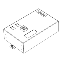
Installation (Figure 1)
1. Remove the enclosure cover from the case.
2. Remove the knockout in the cover.
3. Mount pilot device support bracket assembly with two
mounting screws in location A (Size 1) or B (Size 2 and 3),
tighten screws to 25 lb.-in.
4. For pushbutton 3-wire control, make electrical connections
per Figure 2.
5. For the 2 and 3 position selector switches, make electrical
connections as shown in Figures 3, 4, 5, and 6.
6. Location of auxiliary interlocks may differ from diagrams,
therefore, markings on units should be followed.
7. Affix the appropriate legend label onto the cover next to the
pilot device.
<> -
NEMA
( )
- Sirius 3R IEC
[ ]
- Sirius
Sof
t st
ar
t
Figure
2
Figure
3
Figure
4
Wire Terminal Product Designation
Figure 5
Figure 1
If a Class 14 NEMA starter is mounted in the enclosure, orient the
pilot device contact blocks as shown in Figure 7. This will prevent
interference between the contact blocks and the ESP200 overload.
Instructions
March 2024
Supersedes Issue of
October, 2021
Hazardous voltage.
Can cause death, serious personal injury, or
property damage.
Disconnect power before working on this equipment.
WARNING