Technical Instructions Powermite 599 Series MT Series SAS Electronic Valve Actuator 24V Proportional Control
Document No. 155-682
January 19, 2016
Page 4 Siemens Industry, Inc.
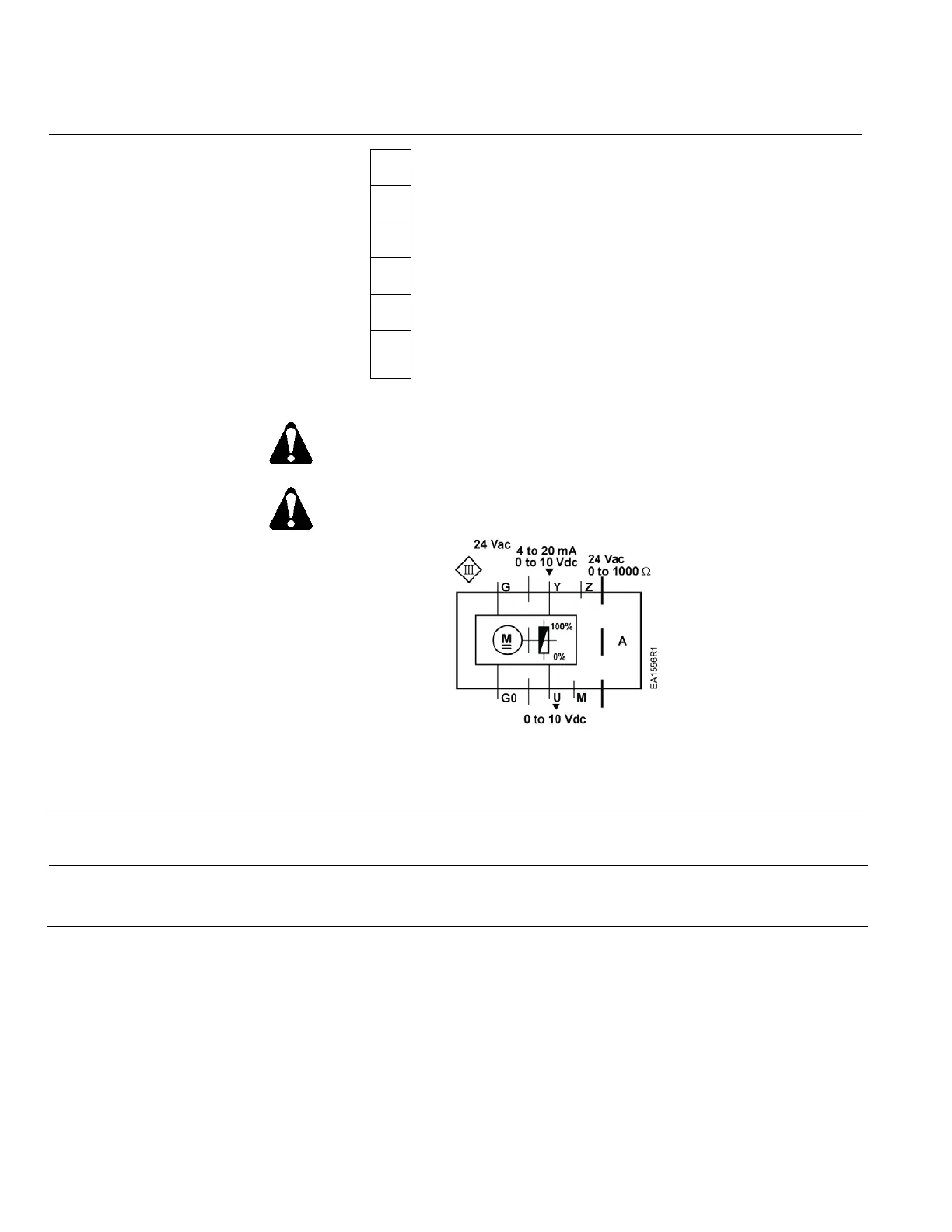
Wiring Diagrams
G0
Neutral (-)
G
Hot (+)
Y
Positioning signal for 0 to 10 Vdc/4 to 20 mA
M
Measuring neutral
U
Position feedback 0 to 10 Vdc
Z
Positioning signal forced control AC/DC ≤ 24V,
0 to 1000 Ω
Figure 2. Terminal Connections.
Terminal connection G is 24 Vac HOT, not ground.
CAUTION:
G0 and G must be properly wired for correct function and full life of the
actuator.
Figure 3. Wiring Diagram.
The diagram shows all possible connections. The application determines which
connections are used.
Start-up
The valve body (normally open or normally closed) determines the action of the
complete valve/actuator assembly.
Troubleshooting
• Check wiring for proper connections and secure attachments.
• Check for adequate power supply.

 Loading...