Always wear an electro-static
discharge (ESD) wrist strap and
discharge accumulated static before
touching field panel components.
Prerequisites
Driver hardware is installed according to its
respective installation instructions.
FLN Termination blocks installed, if any.
One AC power receptacle for each
communication interface adapter or device.
Depending on the type of installation, other
prerequisites may have to be completed.
Connecting the Driver to the
Vendor's Modbus Master or
Modbus Slave Devices
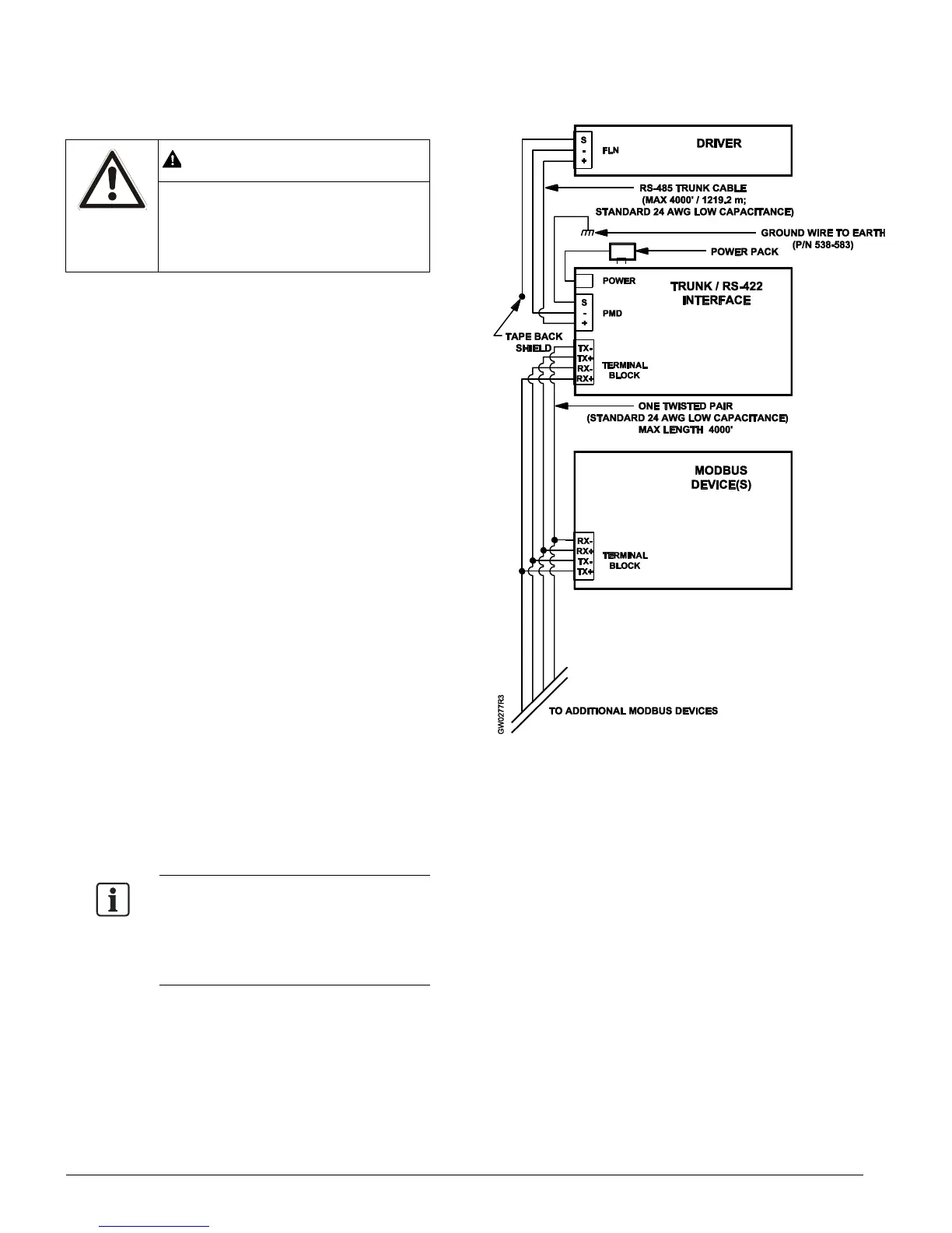
Follow these steps to connect the Modbus and
Modbus 250/500/1000 Driver to Modbus devices:
1. Make cables per the diagram in Figure 1,
Figure 2, or Figure 3.
2. If applicable, install the Trunk/RS-422 or Trunk
Interface II per the diagram in Figure 1 or
Figure 2.
3. Connect cables per the diagram in Figure 1,
Figure 2, or Figure 3.
4. If applicable, plug in the power supply for the
Trunk/RS-422 or Trunk Interface II per the
diagram in Figure 1 or Figure 2.
NOTE:
For Modbus over Ethernet, use IEEE
802.3 standard Ethernet connections
and cabling to complete your network
infrastructure.
 Loading...