Operating modes
The following operating modes are available:
Normal operation
In Normal operation, the controller maintains the setpoint, which can be adjusted via
the + - buttons. The fan can be set to automatic or manual fan speed: Low, medium or
high.
The setpoint setting range can be limited to a minimum (P05) and maximum (P06). This
helps prevent the waste of energy, thus saving costs.
Tip!
Standby
When the controller is in Standby mode
, the relevant setpoints of heating or cooling
are maintained. These setpoints can be adjusted via control parameters P03 and P04.
Factory setting of both setpoints is OFF, which means that the controller is not acti-
vated when in Standby mode.
In Auto Timer mode
AUTO
, the controller will automatically change over between Normal
operation and Energy Saving mode according to the 8 preprogrammed timers. The
display shows the Auto Timer mode symbol
AUTO
and the symbol of the operating mode
currently maintained, either Normal operation
or Energy Saving mode
.
The setpoints of Energy Saving mode can be adjusted via control parameters
P01 and P02.
The default fan speed in Auto Timer mode is automatic fan.
Auto Timer mode
AUTO
(only with RDF410.21)
Energy Saving mode
To avoid damage due to moisture in very warm and humid climatic zones resulting from
lack of air circulation in Energy Saving mode, the fan can be kept running all the time
(e.g. in apartments or shops during unoccupied periods), when setting parameter P20
“ON in dead zone”. In this case, the fan keeps running at minimum fan speed 1.
Avoiding damage
due to moisture
Control sequences
Used in conjunction with a valve, either for heating / cooling with changeover, heating
only or cooling only.
Water-based fan coil
application
Used in conjunction with a 1-stage compressor for cooling only or heating only.
Compressor based
application
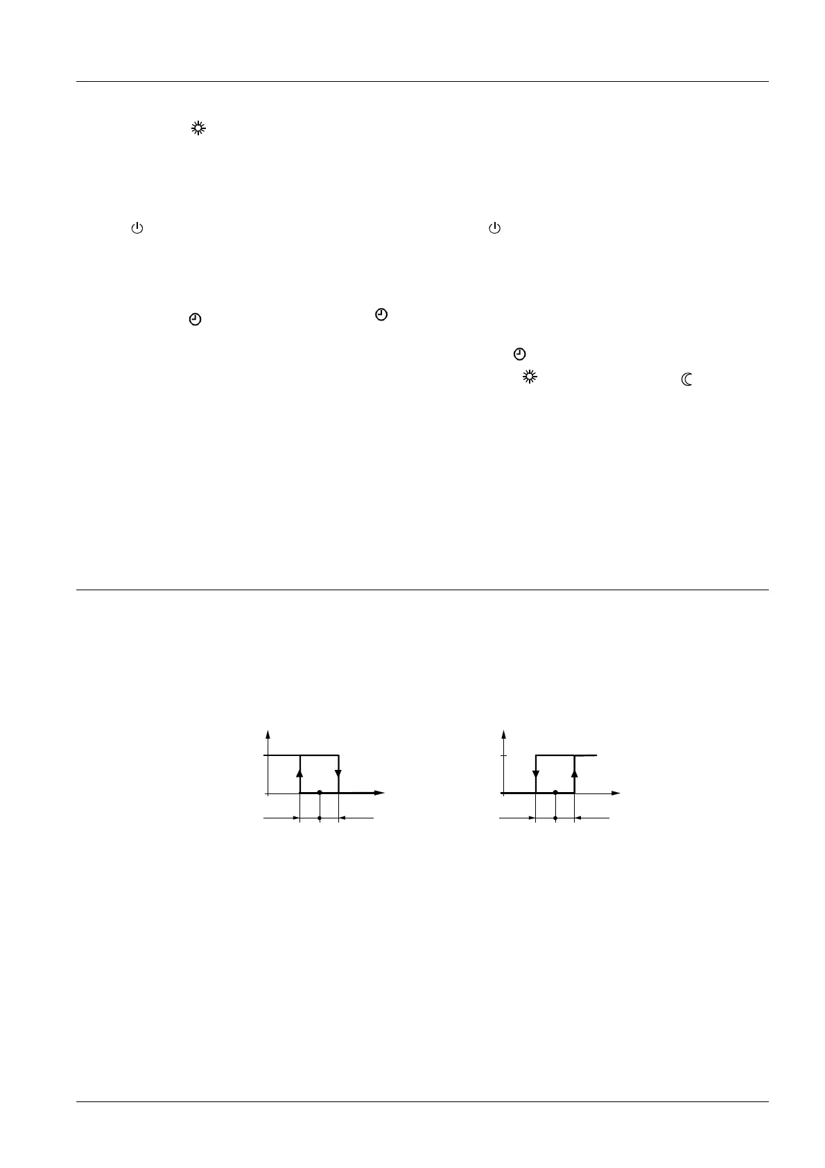
Heating mode Cooling mode
½ SDH
1
0
½ SDH
w
11
3057D02
T[°C]
½ SDC
1
0
½ SDC
w
11
3058D02
T[°C]
T[°C] Room temperature SDH Switching differential “Heating”
W Room temperature setpoint SDC Switching differential “Cooling”
Y11 Control output “Valve” or “Compressor”
The valve or compressor receives the OPEN command via control output Y11 when
ON
1. the acquired room temperature lies by half the switching differential below the set-
point (heating mode) or above the setpoint (cooling mode), and
2. control output Y11 was not energized for more than the “Minimum output off time”
(factory setting 1 minute, adjustable via parameter P16)
The valve or compressor receives the CLOSE command via control output Y11 when
OFF
1. the acquired room temperature lies by half the switching differential above the set-
point (heating mode) or below the setpoint (cooling mode), and
3/14
Siemens Room Temperature Controllers N3067en
Building Technologies 01.10.2007

 Loading...