10/12
Siem ens Room temperature controllers CE1N3072en
Building Technologies 2014-04-04
Connection diagram
L Live, AC 230 V
Lx Live, AC 24…250 V
L1 N.O. contact, AC 24…250 V / 8 (3) A
L2 N.C. contact, AC 24…250 V / 8 (3) A
M1 Circulating pump
N Neutral conductor
Nx Neutral conductor
N2 Receiver RCR10/433
Y1 Actuating device
L – N AC 230 V / Lx – Nx AC 24…250 V
Application examples
Wireless room temperature controller with
receiver control of a gas-fired wall-hung
boiler
Wireless room temperature controller with
receiver control of atmospheric gas burner
Y1
M1
N2
T
N1
Wireless room temperature controller with
receiver control of a heating circuit pump
(precontrol by manual mixing valve)
F1 Thermal reset limit thermostat
F2 Safety limit thermostat
M1 Circulating pump
E1 Cooling equipment
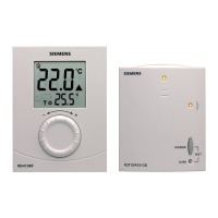
N1 Room temperature controller RDJ10RF
N2 Receiver RCR10/433
Y1 3-port valve with manual adjustment
Y2 Magnetic valve

 Loading...