5.6 Fitting an extender
Position
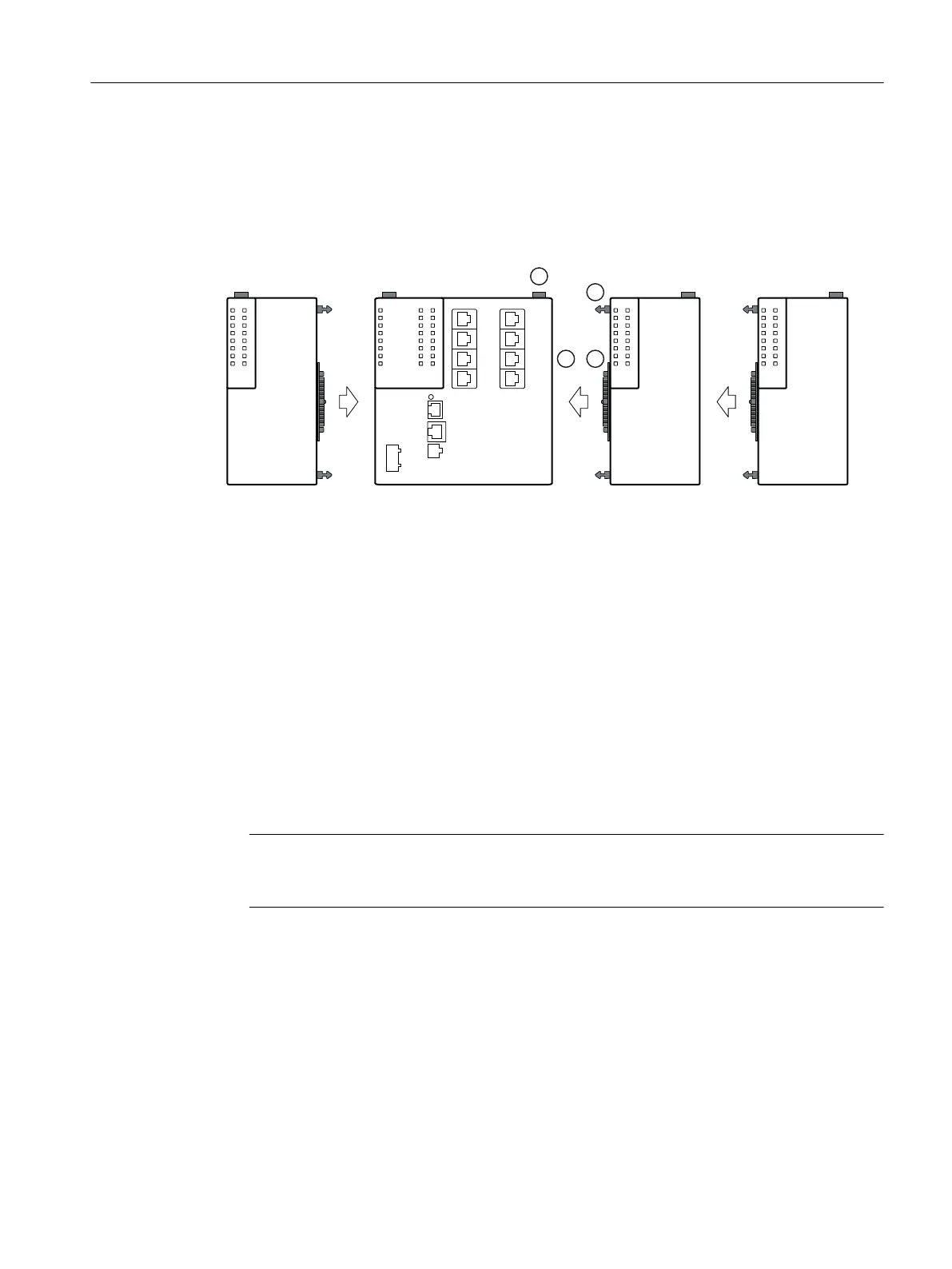
The following gure shows the elements required to connect two devices.
① Locking mechanism (on the rear of the device)
② Centering pin
③ Multipole connector for connection to the expansion interface
④ Expansion interface with cover
Via the expansion interface, the basic device supplies the extenders with power and manages
the ports of the extenders.
The power provided by the PE408PoE port extender for Power over Ethernet does not come from
the basic device. Connect an external power source, see e.g. section "Accessories (Page 23)".
Types of installation
You have the following options when connecting devices:
• You can connect the devices and mount them together on a DIN or S7 standard rail.
• You can mount a device on a DIN or S7 standard rail and expand it later.
Note
For mounting on a rail as well as for removing from the rail, plan enough space between the
devices, see section "Extender dimension drawings (Page 78)".
Installation
5.6 Fitting an extender
SCALANCE XM-400
Operating Instructions, 03/2021, C79000-G8976-C306-10 49
 Loading...