SIMATIC S5 CPU Direct Driver
GP-Pro EX Device/PLC Connection Manual
14
5 Cable Diagram
The cable diagram shown below may be different from the cable diagram recommended by Siemens AG. Please
be assured there is no operational problem in applying the cable diagram shown in this manual.
• The FG pin of the main body of the External Device must be D-class grounded. Please refer to the manual of
the External Device for more details.
• SG and FG are connected inside the Display. When connecting SG to the External Device, design the system
not to form short-circuit loop.
• Connect the isolation unit, when communication is not stabilized under the influence of a noise etc..
Cable Diagram 1
1A)
Display
(Connection Port)
Cable Remarks
GP3000 (COM1)
GP4000
*1
(COM1)
SP5000
*2
(COM1/2)
SP-5B00 (COM1)
ST (COM1)
LT3000 (COM1)
IPC
*3
PC/AT
*1 All GP4000 models except GP-4100 Series and GP-4203T
*2 Except SP-5B00
*3 Only the COM port which can communicate by RS-232C can be used.
)" IPC COM Port" (page 4)
1A
SIEMENS TTY converter cable by Pro-face
CA6-CBLTTY/5M-01 (5m)
GP-4105 (COM1)
GP-4115T (COM1)
GP-4115T3 (COM1)
1B
User-created cable
+
SIEMENS TTY converter cable by Pro-face
CA6-CBLTTY/5M-01 (5m)
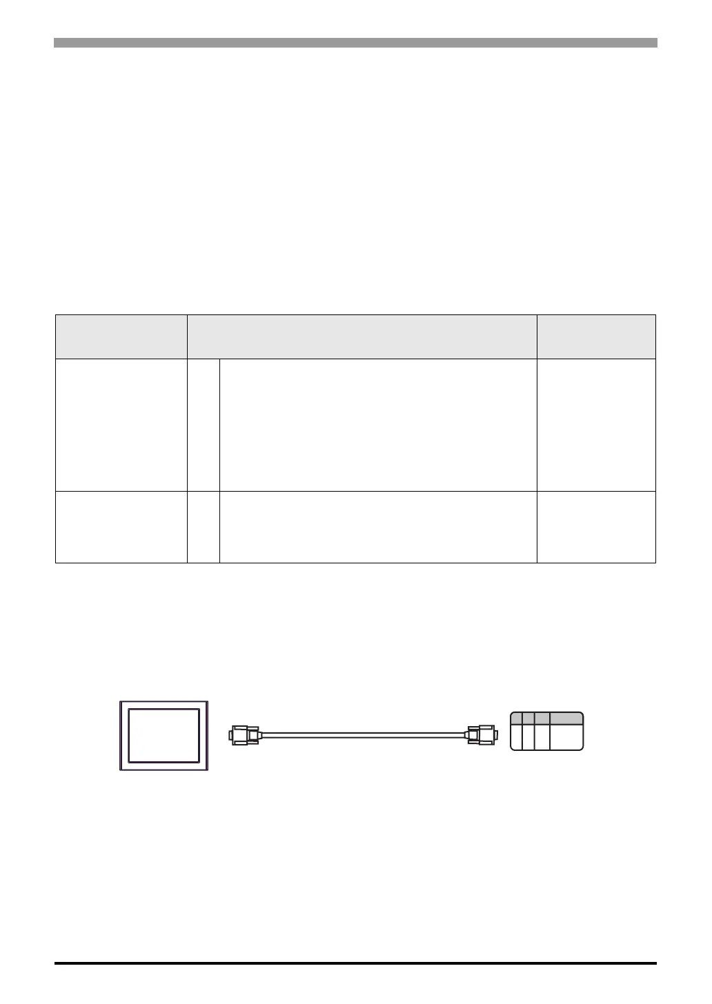
Display
External Device
CA6-CBLTTY/5M-01
 Loading...


