Configuration
3.3 Dimensioning
For motion control and technology functions (e.g. positioning), as well as for synchronous
functions, the corresponding automation system, e.g. SIMOTION D, is used.
The drives are interfaced to the higher-level automation system via PROFIBUS.
3.3.3 3. Definition of the load, calculation of max. load torque, definition of the motor
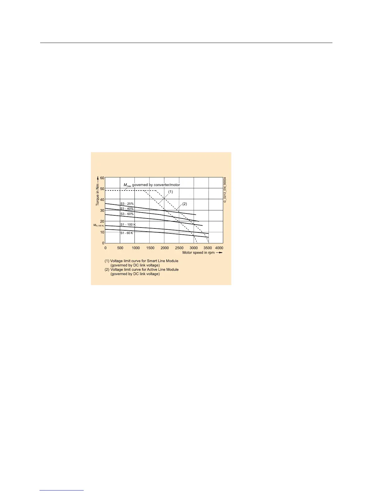
The motor-specific limiting curves are used as basis when selecting a motor.
These define the torque characteristic with respect to speed and take into account the motor
limits based on the line supply voltage and the function of the infeed.
Figure 3-1 Limiting curves for synchronous motors (example)
The motor is selected based on the load which is specified by the application. Different
characteristics must be used for different loads.
The following operating scenarios have been defined:
• Load duty cycles with constant on period
• Load duty cycles with varying on period
• Load duty cycle
The objective is to identify characteristic torque and speed operating points, on the basis of
which the motor can be selected depending on the particular load.
Once the operating scenario has been defined and specified, the maximum motor torque is
calculated. Generally, the maximum motor torque is required when accelerating. The load
torque and the torque required to accelerate the motor are added.
General Section for Synchronous Motors
3-6 Configuration Manual, (PJAL), 11.2005 Edition, 6SN1 197-0AD07-0BP4
 Loading...


