Siemens Industry, Inc.
Building Technologies Division
P/N 315-034170-134
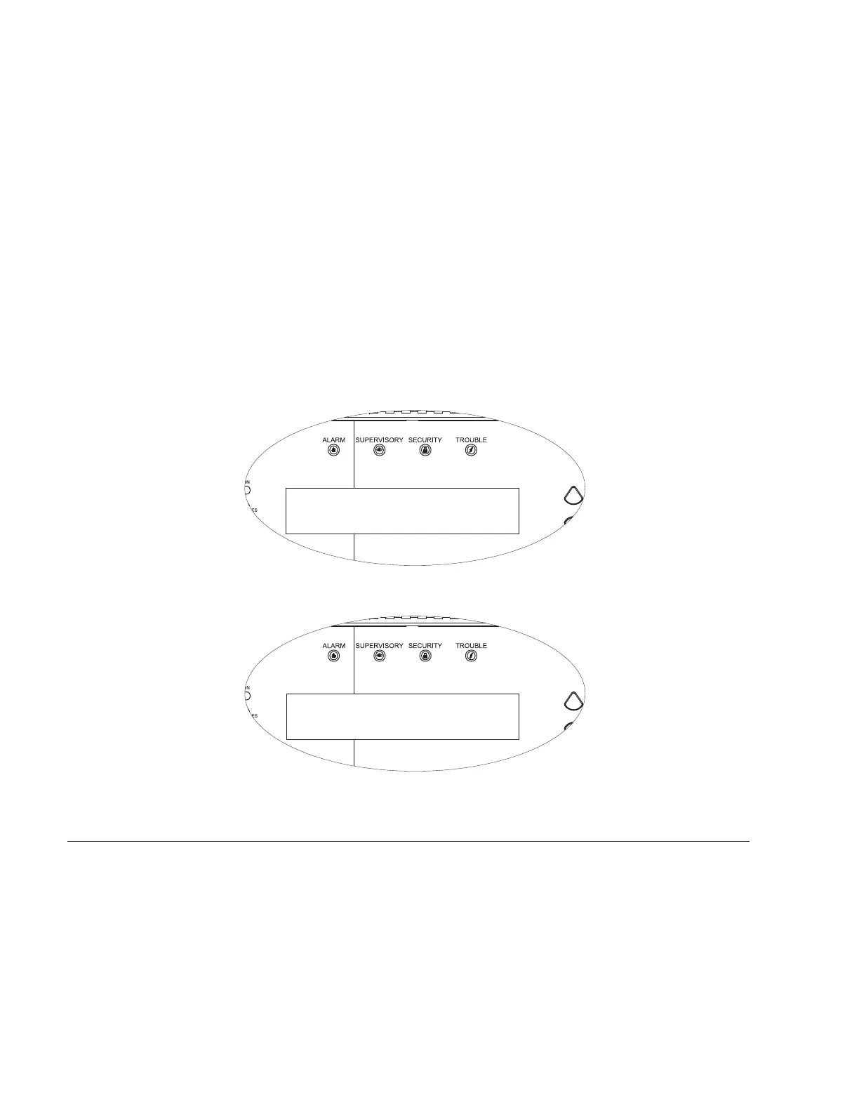
LCD (See Figure 3.) The LCD backlight activates for 10 minutes when an
event occurs or when a push button is pressed.
Supervisory Mode:
Line 1 - Current date and time
Line 2 - Custom message and system ID
Line 3 - Custom message and system ID
Line 4 - Blank
Active Event Mode:
Line 1 - Event Status, module/device address, date and
time of the event
Line 2 - Custom message for the module/device,
acknowledged/non-acknowledged
Line 3 - Event category or trouble type, sequence
number of the event.
Line 4 - Total number of Alarms, Supervisory, Security,
and Trouble events in the system or vectored to
the SSD.
may 15, 2002 , 04:10:52pm
custom message - system id #1
custom message - system id #2
system
normal
may 16, 2002 , 04:15:25pm
custom message for this alarm ack’d
alarm 3-45
smoke 001 of 200
alm=200 supv=000 sec=000 trbl=000
Figure 3
SSD LCD - Supervisory Mode (Top) and Active Event Mode (Bottom)
PRE-INSTALLATION The following components must be set prior to installing the SSD housing enclosure
to the SSD mounting plate. Refer to Figure 4.
S1 Option Select DIP Switch:
S1-SW1: Set to ON if the SSD is the end of the PAIR A wiring (Style 4 only)
S1-SW2: Set to OFF: Not Used
S1-SW3: Set to OFF: Not Used
S1-SW4: Set to OFF: Not Used
 Loading...