SilverCrest SHLF 2000 C1
26 - English
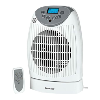
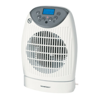
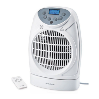
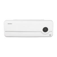
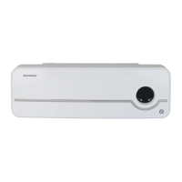
3. Overview of the operating controls
These operating instructions have a fold-out cover. On the inside of the cover is a diagram of the
fan heater with the components numbered. The meanings of the numbers are as follows:
1 Control panel
2 Air outlet grille
3 Base
4 Safety switch (on the bottom)
5 Handle
6 Air inlet grille
7 Remote control compartment
8 Main power switch
9 Power cable (with Velcro to keep the power cable together)
10 Display
11
On/Standby button
12
+
Value up (temperature / time)
13
–
Value down (temperature / time)
14 Power indicator
15 Infrared remote sensor
16
Switch timer on/off
17
Switch swivel function on/off
18
Mode
Set operating mode
19 Remote control
20 Infrared transmitter
21
Mode
Set operating mode
22
Switch timer on/off
23
–
Value down (temperature / time)
24
+
Value up (temperature / time)
25
Switch swivel function on/off
26
On/Standby button
Display items
27 Swivel function is on
28 Automatic mode: the heat output is automatically adjusted to the room temperature (33).
As soon as the set target temperature (34) is reached, the fan heater automatically
switches off.
29 Low power: Fan heater working at 1000 Watt
30 High power: Fan heater working at 2000 Watt
31 Frost monitor switched on
32 Timer
33 Displays current room temperature
34 Displays the target temperature set
 Loading...