 Loading...
Do you have a question about the Sinee A90-4T075 and is the answer not in the manual?
Details the rated voltage, applicable motors, and provides a table of inverter models and their specifications.
Explains the different working statuses and running modes of the A90 series inverter, including control laws.
Guides on how to check the inverter product upon receipt, including nameplate and component verification.
Provides detailed outline and installation dimensions for various A90 series inverter models with diagrams.
Specifies environmental conditions, attention points, and requirements for the installation site.
Details the correct installation direction and required clearance for proper heat dissipation.
Illustrates the standard connection diagram of the A90 series inverter with peripheral devices.
Details the composition, functions, and standard wiring diagrams of the main circuit terminals.
Explains the composition and functions of control circuit terminals with wiring diagrams.
Describes the structure of the LED keyboard and the functions of its keys and indicators.
Explains the different menu levels and parameter display modes of the keyboard interface.
Details how to monitor faults directly using the right shift key when the inverter is in a fault status.
Explains how to view and switch monitoring parameters using function codes F12.33 to F12.37.
Describes the multiple response modes of the M.K multi-function key, defaulting to jog forwarding.
Explains how to use the RUN and STOP/RESET keys to start and stop the inverter after parameter settings.
Provides a flowchart for the inverter commissioning process, from installation to final inspection.
Lists essential items to confirm regarding power wiring, motor wiring, and control terminals before powering on.
Describes the normal status display information shown on the inverter's control panel after power-on.
Details precautions for selecting industry application macros using F16.00 and their activation via F12.14.
Explains various methods for controlling the inverter's start and stop operations.
Explains the organization of function codes into groups and the purpose of different groups.
Provides a detailed table listing all functional parameters, their descriptions, units, default settings, and attributes.
Details basic function parameters including drive control mode and command source selection.
Covers motor parameters for Motor 1, including type, power, voltage, current, and winding connection.
Details the functions and configurations of digital and analog input terminals (X1-X5, AI1, AI2).
Explains the functions and configurations of the multi-function digital output terminal (Y1) and relay output (R1).
Details parameters for controlling inverter start-up methods, frequency, DC braking, and speed tracking.
Covers V/F curve settings, voltage source selection, and compensation parameters for V/F control.
Details parameters for vector control, including speed proportional and integral gains, and switching frequencies.
Defines parameters for fault protection, including overload, overvoltage, undervoltage, and load loss.
Explains parameters for multi-segment speed control and simple PLC functions.
Details parameters for PID control, including setting sources, gains, and switching conditions.
Covers Modbus communication parameters like address, baud rate, data format, and timeout settings.
Allows users to define shortcuts to frequently accessed function codes for personalized operation.
Details parameters related to keyboard functions, display modes, and parameter locking.
Covers parameters for torque control, including setting sources, limits, and acceleration/deceleration times.
Provides parameters for a second motor, allowing independent configuration of drive modes and control.
Details auxiliary functions such as jog control, acceleration/deceleration time switching, and frequency hopping.
Explains parameters for virtual input and output terminals, enabling flexible logic configuration.
Lists parameters for monitoring inverter status, including output frequency, current, voltage, and bus voltage.
Provides access to view the types of the last three faults and the inverter status at the time of failure.
Explains the necessity and process of self-identifying motor parameters for improved control accuracy.
Lists important precautions before performing motor parameter self-identification, such as stopping the motor.
Provides step-by-step instructions for performing static and rotary self-identification of motor parameters.
Lists fault codes, their causes, and corresponding solutions for A90 series inverters.
Analyzes common failures related to parameter settings and motor rotation, providing troubleshooting steps.
Outlines daily inspection procedures, cleaning, and checks for normal operation.
Provides information on inverter warranty services and conditions for maintenance fees.
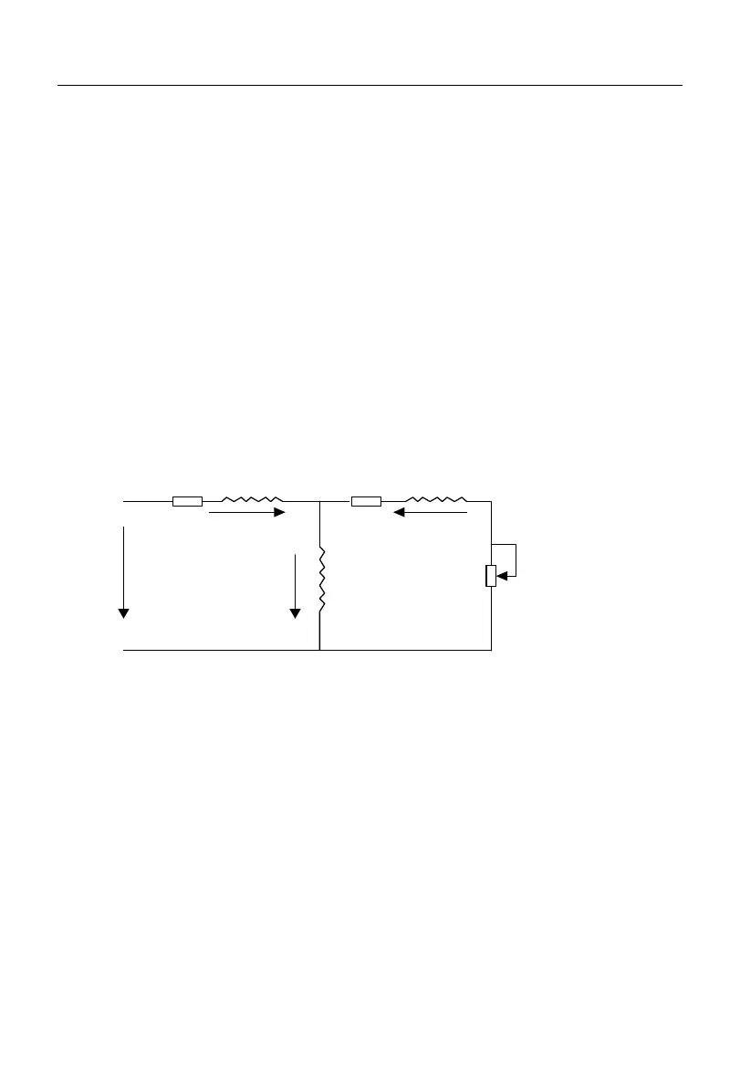
Explains the purpose of braking resistors and provides a formula for calculating resistor power and typical load conditions.
Details the available BR100 series braking units and their specifications for A90 series inverters.
Provides wire specifications for braking units and resistors, including insulation and cross-section requirements.
Defines the applicable series (A90) and network types (single-master multi-slave) for Modbus communication.
Specifies the RS-485 communication mode, network address, default data format, and baud rate.
Details the structure of Modbus RTU messages, including message format, address codes, and function codes.