7
1. PROBLEM: Valve does not function (red light does not flash
when user steps in front of sensor).
CAUSE: No power is being supplied to sensor.
SOLUTION: Ensure that the main power is turned “ON.” Check transformer,
leads and connections. Repair or replace as necessary.
CAUSE: EL-1500 series sensor is not operating.
SOLUTION: Replace EL-1500 series sensor.
2. PROBLEM: Valve does not function (red light flashes when user
steps in front of Sensor).
INDICATOR: Red light stops flashing when user steps away and
valve makes a “clicking” sound but does not flush.
CAUSE: No water is being supplied to the valve.
SOLUTION: Make certain that water supply is turned “ON” and the Control
Stop is open.
CAUSE: EL-128-A cartridge is fouled or jammed.
SOLUTION: Turn electronic power to valve “OFF” (failure to do so could result
in damage to the solenoid coil). Remove the solenoid operator
from the valve and remove the EL-128-A cartridge. Clean and/or
repair as necessary.
INDICATOR: The red light stops flashing when user steps away
but the valve does NOT make a “clicking” sound
and does NOT flush.
CAUSE: EL-163-A solenoid shaft assembly is fouled or
jammed.
SOLUTION: Turn electronic power to valve “OFF” (failure to do so could result
in damage to the solenoid coil). Remove EL-101 or EL-166 nut
from the solenoid operator. Remove the coil from the solenoid
operator. Use a spanner wrench or pliers to remove the EL-163-A
solenoid shaft assembly from valve. Clean and/or replace as
necessary. Be sure to replace plunger spring when reassembling
solenoid shaft assembly.
INDICATOR: Theredlightflashesthree(3)shortflashes,three(3)
long flashes then three (3) short flashes (“S-O-S”)
and continues to repeat this cycle even when user
steps out of the sensor’s detection range.
CAUSE: EL-1500 Series Sensor wiring connections are
incorrect.
SOLUTION: Rewire sensor to valve. One solenoid lead connects to the “TO
VALVE” connection on sensor. One transformer lead connects to
the “24 VAC IN” connection on sensor. Second solenoid lead and
second transformer lead connect together.
CAUSE: Wiring to Sensor is ground shorted.
SOLUTION: Find short in wiring circuit and correct.
CAUSE: EL-165-2 solenoid coil is burnt out or coil is not
connected to solenoid plunger shaft.
SOLUTION: Reinstall or replace coil as necessary.
3. PROBLEM: Volume of water is insufficient to adequately
siphon fixture.
CAUSE: Control stop is not open wide enough.
SOLUTION: Adjust control stop for desired water delivery.
CAUSE: Low consumption unit is installed on water saver
or conventional fixture.
SOLUTION: Replace diaphragm component parts of valve with kit that
corresponds to appropriate flush volume of fixture.
CAUSE: Inadequate water volume or pressure available
from supply.
SOLUTION: Increase pressure or supply (flow rate) to the valve. Consult
factory for assistance.
4. PROBLEM: Length of flush is too long (long flushing) or
valve fails to shut off.
CAUSE: Water saver valve is installed on low
consumption fixture.
SOLUTION: Replace Diaphragm component parts of valve with kit that
corresponds to appropriate flush volume of fixture.
CAUSE: Relief valve in diaphragm is not seated properly
or bypass hole in diaphragm is clogged.
SOLUTION: Disassemble inside Diaphragm component parts and wash parts
thoroughly. Replace worn parts if necessary.
5. PROBLEM: Water splashes from fixture.
CAUSE: Supply flow rate is more than necessary.
SOLUTION: Adjust control stop to meet flow rate required for proper cleansing
of the fixture.
When further assistance is required, please contact Sloan Technical Support at:
1-888-SLOAN-14 (1-888-756-2614)
or visit us online at:
www.sloanvalve.com
NOTE: URINALS – When the sensor detects a user, a slow flashing red light appears in the sensor window. After eight (8) to ten (10) seconds, the light flashes
rapidly to indicate that the sensor is armed. When the sensor no longer detects a user, the sensor immediately activates the solenoid valve after a 0.5 second delay.
WATER CLOSETS – Detection and activation are the same as the urinal except when the sensor no longer detects an user, the sensor activates the solenoid
valve after a three (3) second delay.
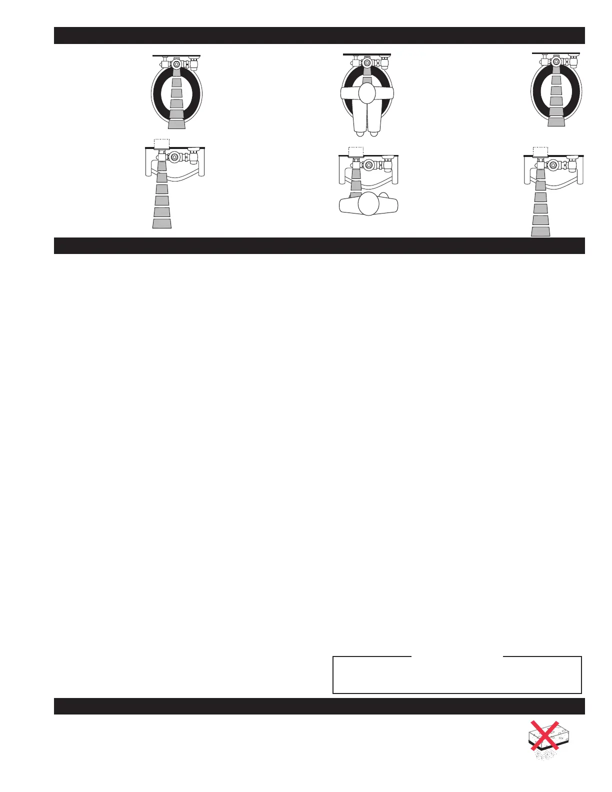
1. A continuous, invisible
light beam is emitted
from the OPTIMA
Sensor.
2. When a user enters the beam’s
effective range, for water closets
22” - 42” (559 mm - 1067
mm) and for urinals 15” - 30”
(381 mm - 762 mm), the
beam is reflected into the
OPTIMA’s scanning window and
transformed into a low voltage
electrical signal that activates a
ten-second time delay circuit.
The time delay circuit eliminates
false operation from passers-by
in the rest room. Once the time
delay is completed, the output
circuit is alerted and continues
in a “hold” mode for as long
as the user remains within the
effective range of the sensor.
3. When the user steps away
from the OPTIMA Sensor,
the loss of reflected light
initiates an electrical “one-
time” signal that energizes
the Solenoid Operator, and
activates the Flushometer
to flush the fixture. This
occurs on the water closet
approximately three (3)
seconds after indication.
This delay is built into the
Sensor to help prevent false
flushing due to movement by
the user. The circuit for both
water closets and urinals
then automatically resets and
is ready for the next user.
DO NOT use abrasive or chemical cleaners to clean flushometers or sensor window that may dull the luster and attack the chrome or special
decorative finishes of flushometer components. Use ONLY soap and water, then wipe dry with clean cloth or towel.
While cleaning the fixture, protect the exposed flushometer from any splattering of cleaner. Acids and cleaning fluids can discolor or remove
chrome plating.
OPERATION
TROUBLESHOOTING GUIDE
CARE AND CLEANING
LAWS AND REGULATIONS PROHIBIT THE
USE OF HIGHER FLUSHING VOLUMES THAN
LISTED ON FIXTURE OR FLUSHOMETER.
!!! IMPORTANT !!!
 Loading...