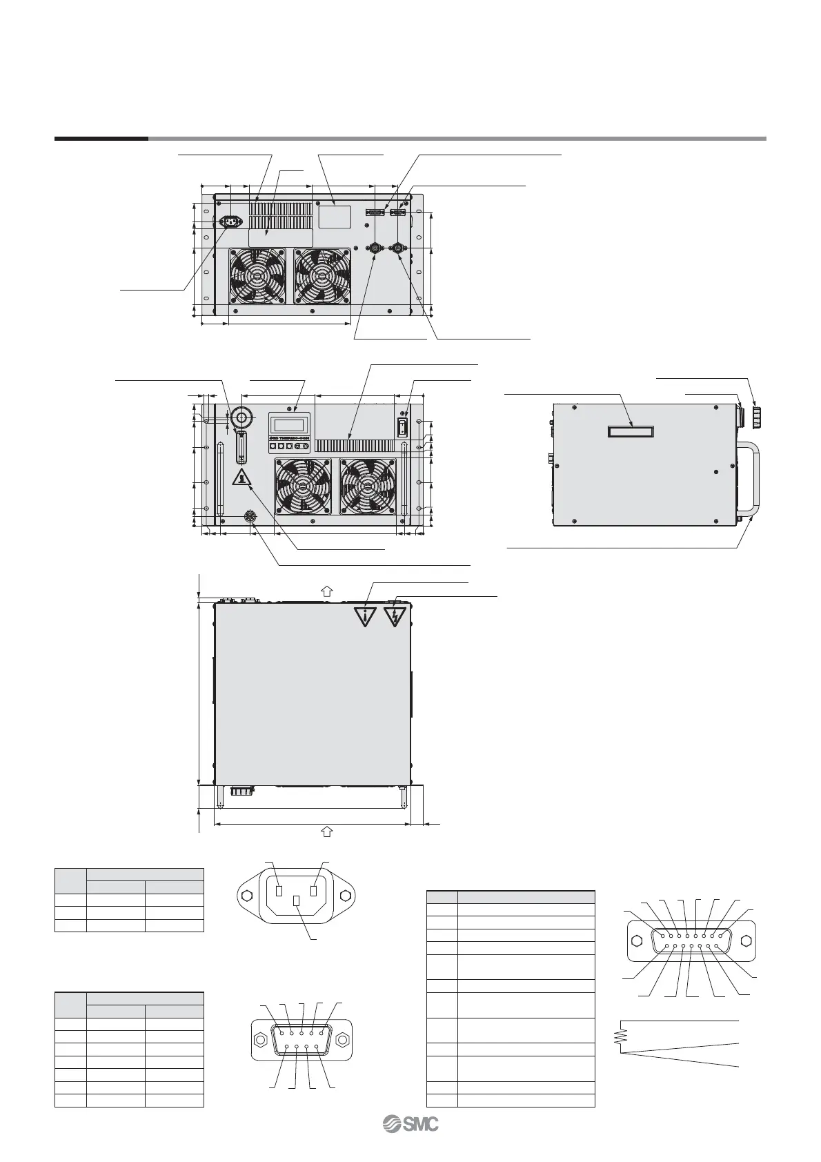
Model no. label
External temperature sensor connector
Alarm output connector
Communication connector
Label
Power supply
connector
Ventilation hole (air outlet)
Circulating fluid drain port CPC PLCD 16004
Caution label/High temperature
Circulating fluid outlet
Rc 3/8
Circulating fluid inlet
Rc 3/8
Air
Air
Caution label/Electricity
Warning/Caution label
Display/
Operation panel
Circulating fluid level gauge
Ventilation hole (air inlet)
Power switch
Fluid fill port
Handle (for carrying the product)
Tank lid (with gasket)
Handle (for installing/removing the product to/from the rack)
(10)400(50)
430 27
10
7
0
237
64
398
237
20
228.5
267
171.3
95.2
0
38
188 (247)
228.5
149
162 (221)
( ): For HECR008
171.3
95.2
38
0
24
444
42
379
474.5
9.5
484
326
0
59
206
247
191
149
0
24
63
429
379
242
0
104
226
148
0
24
326
0
59
NL
E
5
4
3
2
1
6
7
8
9
Connection diagram of
resistance tem
erature sensor
8
7
6
5
4
3
2
1
9
10
11
12
13
14
15
5
4
3
Dimensions
HECR008-A5
HECR010-A2
1. Power supply connector
IEC60320 C14 (or equivalent)
2. Communication connector
D-sub 9 pin (socket)
Holding screw: M2.6
3.
External temperature sensor connector/Alarm output connector
D-sub 15 pin (socket)
Holding screw: M2.6
Pin no.
Signal contents
HECR008 HECR010
N
100-240 V AC 200-240 V AC
L
100-240 V AC 200-240 V AC
E PE PE
Pin no.
Signal contents
RS-232C RS-485
1 Unused BUS+
2 RD Unused
3 SD Unused
4 Unused Unused
5 SG SG
6-8 Unused Unused
9 Unused BUS–
Pin no.
Signal contents
1-2 Unused
3
Terminal A of resistance temperature detector
4
Terminal B of resistance temperature detector
5
Terminal B of resistance temperature detector
6
Contact a for output cutoff alarm
(open when alarm occurs)
7
Common for output cutoff alarm
8
Contact b for output cutoff alarm
(closed when alarm occurs)
9
Contact a for upper/lower temp. limit alarm
(open when alarm occurs)
10
Common for upper/lower temp. limit alarm
11
Contact b for upper/lower temp. limit alarm
(closed when alarm occurs)
12-14 Unused
15 FG
17
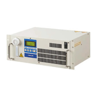
Series HECR
 Loading...