Alarm
code
Alarm description
Operation
status
Main reason
WRN Upper/Lower temp. limit alarm Continue The temperature has become out of upper/lower limit range for the target temperature.
ERR01 System error 1 Stop
The internal cable of the thermo-con has been broken due to abnormal vibration or dropping the product.
ERR02 System error 2 Stop EEPROM data has been lost due to high level noise.
ERR03 Back-up data error Stop EEPROM data of the controller has been destroyed due to high level noise.
ERR11 DC power supply failure Stop
The DC power supply has failed (due to fan stop or abnormal high temperature) or the
thermo-module has been short-circuited.
ERR12 Internal temp. sensor high temp. error Stop The internal temperature sensor has become higher than high temp. cutoff setting.
ERR13 Internal temp. sensor low temp. error Stop The internal temperature sensor has become lower than low temp. cutoff setting.
ERR14 Thermostat alarm Stop The thermostat has been activated due to radiator fin clog or fan/pump failure, etc.
ERR15 Abnormal output alarm Continue
The temperature cannot be changed even at 100 % output due to overload or disconnection
of the thermo-module.
ERR16 Low flow rate alarm (Option) Stop The flow rate of the circulating fluid has dropped.
ERR17
Internal temp. sensor disconnection alarm
Stop The internal temperature sensor has been disconnected or short-circuited.
ERR18
External temp. sensor disconnection alarm
Continue
The external temperature sensor has been disconnected or short-circuited. (Only detected
when in learning control or external tune control)
ERR19 Abnormal auto tuning alarm Stop Auto tuning has not been completed within 20 minutes.
ERR20 Low fluid level alarm Stop The amount of circulating fluid in the tank has dropped.
PV
<
ERR11 WRN
SV
31. 6 n C #1
30. 0 n C
MODE Normal
Alarm
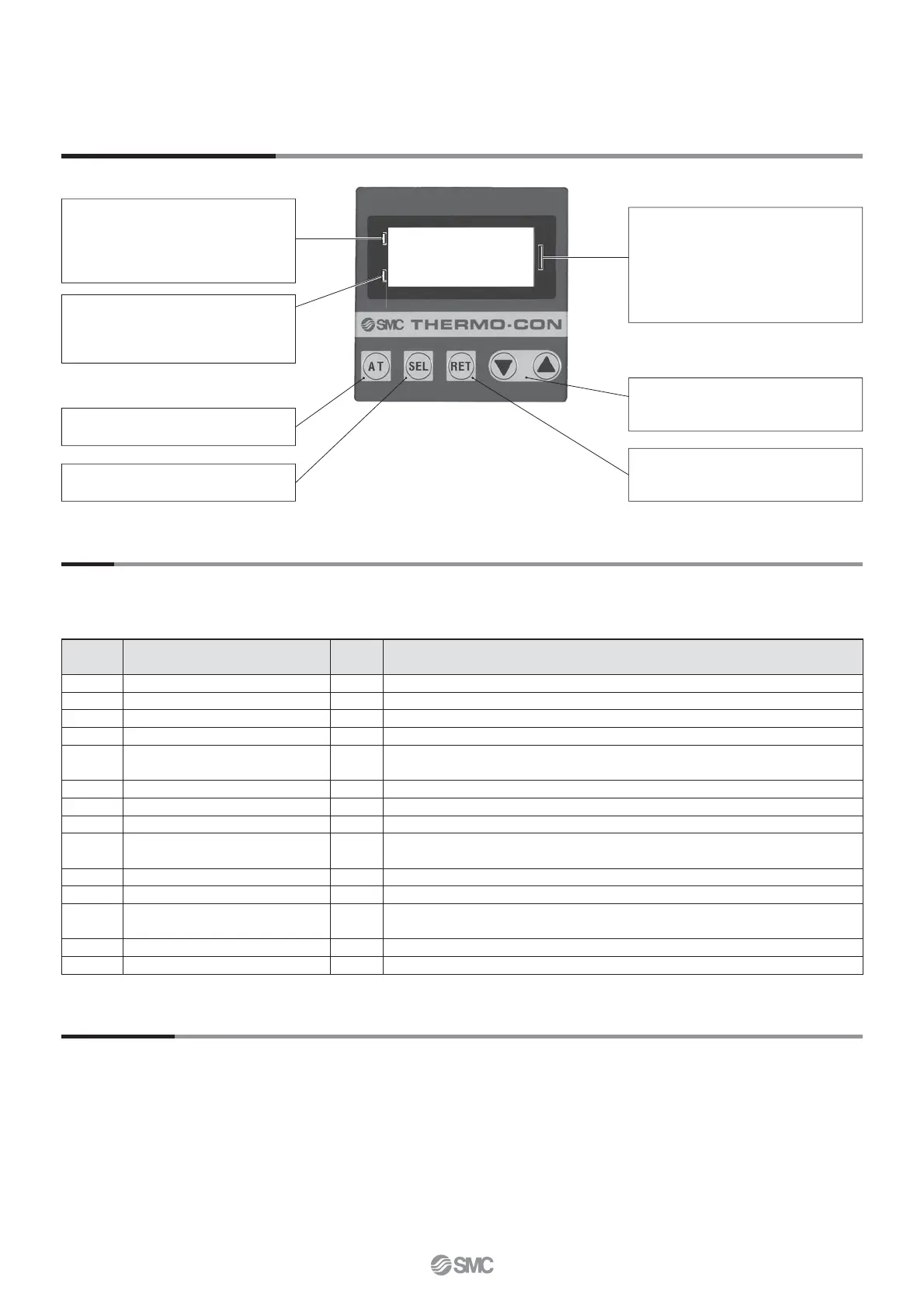
Operation Display Panel
This unit is equipped as standard with a function allowing 14 kinds of alarms to display on the LCD and can be read out by serial
communication. Also, it can generate relay output for upper/lower temperature limit alarm and output cutoff alarm.
AT key
Used to start and stop auto tuning.
key
Used to change set value in each setting
mode.
SEL key
Used to change setting mode.
RET key
Used to fi x set value or return to present
temperature status indication.
Maintenance
Please consult SMC for maintenance
Alarm
1st line
Indicates No. corresponding to the alarm
which arises and [WRN] comes to light
up when the upper or lower temperature
limit warning occurs.
4th line
Indicates control operation mode during
normal operation and set values during
setting mode selection.
2nd, 3rd line
Indicates present temperature [PV] and
target temperature [SV] during normal
operation. When the alarm arises, the
error is indicated instead and during set-
ting mode selection, the selected setting
mode is indicated.
18
Thermo-con/Rack Mount Type Series HECR
 Loading...