LECP6-TFM107 Draft
3 Specifications
Item Specifications
Compatible motor Step motor (Servo 24VDC)
Controller power supply
Note1)
Rated voltage: 24VDC ±10%
Max current consumption: 3A (
Peak
5A)
Note2)
(For powering the motor drive, controller, stop
and lock release)
Parallel input 11 inputs (photo-coupler isolation)
Parallel output 13 outputs (photo-coupler isolation)
Compatible encoder
A/B phase, Line receiver input
Resolution: 800 pulse/rev
Serial communication Conforming to RS485.
Memory EEPROM
LED indicator 2 off LED’s (green and red):
Lock control Forced lock-release terminal
Cable length (m)
I/O cable: 5 or less
Actuator cable: 20 or less
Cooling system Natural air cooling
Operating temperature range
(
o
C)
0 to 40 (without condensation or freezing)
Operating humidity range (%) 35 to 85 (without condensation or freezing)
Storage temperature range (
o
C) -10 to 60 (without condensation or freezing)
Storage humidity range (%) 35 to 85 (without condensation or freezing)
Insulation resistance
Between the housing (radiation fin) and FG
50MΩ
ΩΩ
Ω (500VDC)
Weight (kg)
0.15 (screw mounting type)
0.17 (DIN rail mounting type)
Note1) Do not use a power supply with “inrush-current control” for the controller
power supply.
Note2) The power consumption changes depending on the actuator model.
Please refer to the specifications of actuator for more details.
4 Installation
• How to install
•Screw mounting type (LECP6**-*) installation using two M4 screws
• DIN-rail mounting type (LECP6**D-*) installation onto the DIN rail
4 Installation (continued)
• Grounding the controller
As shown in the diagram, connect the grounding wire with a screw.
The controller must be grounded to shield it from electrical noise.
The M4 screw, cable with crimping terminal and toothed washer should
be obtained separately by the customer.
Caution
The product should be connected to a ground. The cross-sectional area of
this wire shall be a minimum of 2 mm
2
. The grounding point should be as
near to the controller as possible to keep the wire length short.
5 Names and Functions of individual parts
No. Label Name Description
1 PWR Power LED (green)
Power ON/No alarm: Green light.
The green LED flashes while data (step data/
parameters) is being written.
2 ALM Power LED (red) Power ON/Alarm: Red light.
3 CN5
Parallel I/O
Connector (26 pins)
Used to connect PLC, etc. with the I/O cable.
(11 inputs and COM, 13 outputs and COM)
4 CN4
Serial I/O
Connector (9 pins)
Used to connect the teaching box, PC, etc.
5 CN3 Encoder connector (16 pins)
6 CN2
Motor power connector
(6 pins)
Used to connect the actuator cable.
7 CN1
Power connector
(5 pins)
Used to connect the controller input power
supply with the power supply plug:
Common power (-),
Motor power (+),
Control power (+),
Stop signal (+),
Lock release (+)
8 - Compatible actuator label
The label indicating the applicable actuator
model.
It also indicates the type of the parallel I/O
(PNP/NPN).
9
-
Product label
The label indicating the part number of the
controller.
10 - FG Functional ground
Caution
The green LED flashes while the data (step data/ parameters) is being
written.
Do not turn off the controller input power supply or remove the cable
while the data is being written (while the green LED is flashing).
* The data (step data/ parameters) may not be written correctly.
6 Wiring
Warning
• Do not use the stop signal, "EMG" of controller and stop switch on
the teaching box as the emergency stop of system.
The stop signal, "EMG" of controller and the stop switch on the teaching
box are for decelerating and stopping the actuator.
Design the system with an emergency stop circuit, which complies with
safety standards.
Caution
• Wiring of power supply plug for controller connector CN1
Connect the positive terminal of the 24 VDC controller power supply to
the C24V and M24V terminals of the power supply plug and connect the
negative terminal of the 24 VDC controller power supply to the 0V
terminal of the power supply plug.
• For actuators fitted with a lock, fit a lock release switch
Connect the lock release switch to the supply plug BK RLS terminal.
• See the power supply plug drawing below for connection details
Warning
Do not wire the power supply plug incorrectly as this will result in
damage to the controller.
6 Wiring (continued)
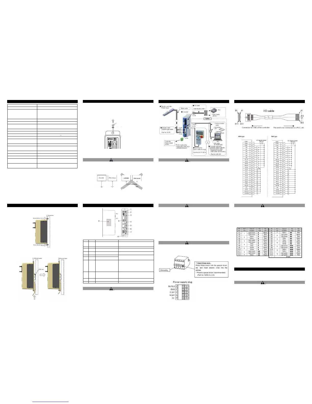
Parallel I/O cable wiring for connection to controller CN5 connector
• Parallel I/O wiring for NPN and PNP connection
Caution
The 24 VDC power supply for the I/O connector CN5 should be separate
from the 24 VDC power supply for the controller connector CN1.
When connecting a PLC etc. to the controller parallel I/O CN5 connector,
use the I/O cable LEC-CN5-*.
• Pin out for I/O cable LEC-CN5-*
7 Maintenance
• Perform a maintenance check periodically
Confirm wiring and screws are not loose.
Warning
• Do not disassemble or repair the product.
Fire or electric shock can result.
• Before modifying or checking the wiring, the voltage should be
checked with a tester 5 minutes after the power supply is turned
off.
Electrical shock can result.
Not recommended: Ground scheme
Recommended: Functional ground

 Loading...


