LECP6-TFM107 Draft
8 CE Directive
The LE series of actuators, motor controllers and teaching box
conform to the EU EMC directive, if they are installed in accordance
with the following instructions.
These components are intended for incorporation into machinery and
assemblies forming part of a larger system.
The CE compliance was achieved when the above three components
were connected as shown in the diagram below.
Please note that the EMC changes according to the configuration of
the customers control panel and the relationship with other electrical
equipment and wiring. Therefore conformity to the EMC directive
cannot be certified for SMC components incorporated into the
customer’s equipment under actual operating conditions. As a result
it is necessary for the customer to verify conformity to the EMC
directive for the machinery and equipment as a whole.
• Machinery parts list
No.
Part name Part no./Material
1 Motor controller LECP6 Series
2 Actuator LE Series
3 Teaching box LEC-T1 Series
4 I/O cable (with shield) LEC-CN5-[]
5 Power supply cable
(with shield)
5 wire with shield
(5 m)
6 Actuator cable LEC-CP-[]
7 P-clip (for shield ground) Metal
8 Programmable controller –
9 Switching power supply –
The LECP6** controller should be mounted in an IP54 rated metal cabinet
for protection from ESD.
The metal cabinet should be grounded with a short grounding cable.
All shielded cables must be grounded inside the cabinet using suitable
metal P-Clip or U-Clip as shown.
The shielded cables are:
• 24 VDC Power cable from power supply to LECP6** series controller
• The Input/output cable from controller to PLC
• Grounding the controller
Please refer to the “Installation” section
8 CE Directive (continued)
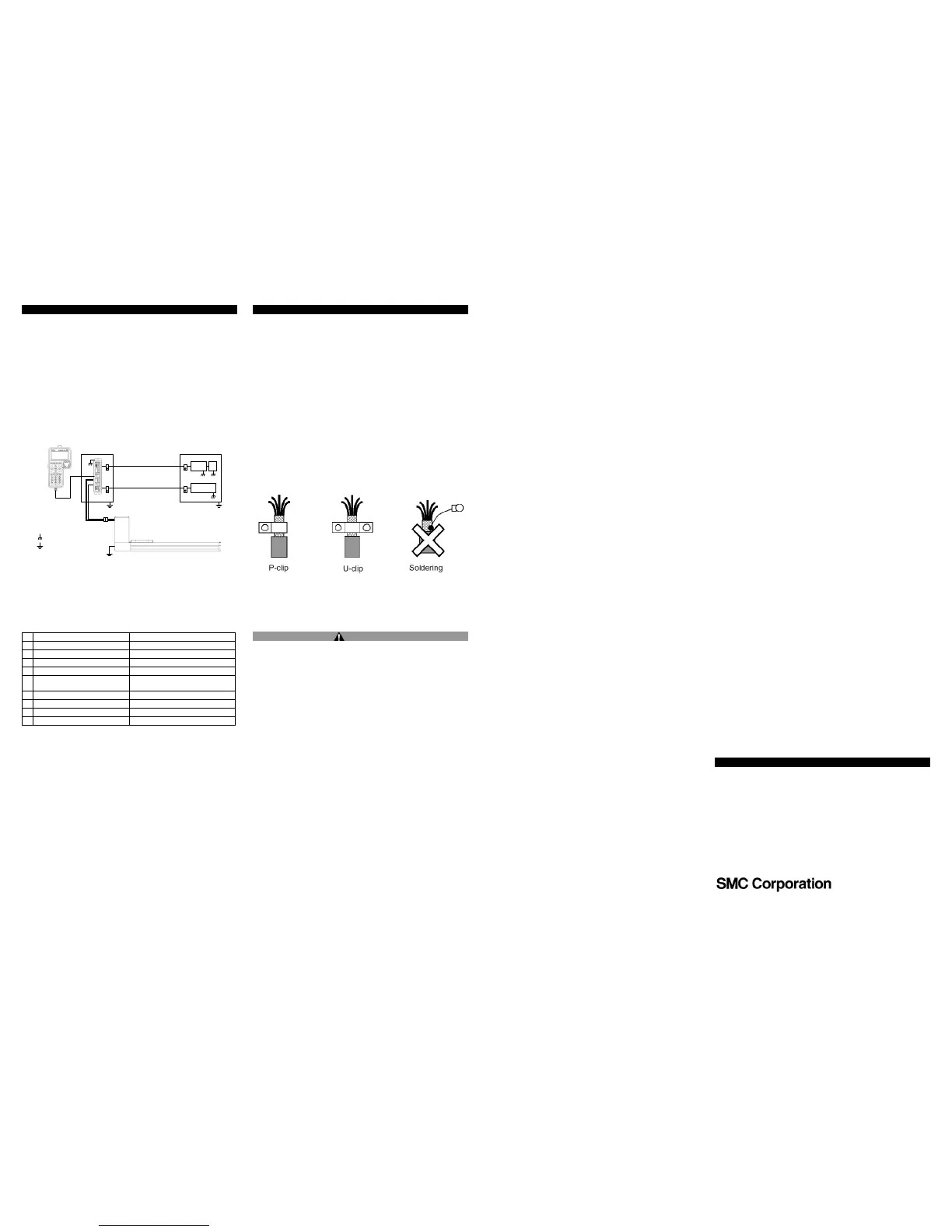
• P-Clip or U-Clip installation
The function of the P-clip or U-clip is to provide a 360° metallic contact
and is a convenient method of ensuring an effective RF ground.
When dealing with EMI issues it is important to know that the DC
connection does not maintain the integrity of an AC high frequency
connection. High frequency bonding typically involves using wide flat
cabling to establish an effective system ground. When applied correctly
the P-clip or the U-clip will provide a high frequency connection.
When installing a P-clip or U-clip (see figure below) install the clips as
close to the cable ends as possible. In order to provide a suitable ground
connection surface, it may be necessary to remove the paint from the
panel or the cabinet, an earth stud or a bus bar are also acceptable.
Remove only the outer vinyl jacket of the braided screened cable (this
allows the cable braid to connect to the P-clip or U clip). Take care not to
damage the braiding. Snap the P-Clip or the U-Clip over the exposed
braiding and adjust for a tight fit. Secure the clip to the designated
ground with a machine screw and lock washer. The use of a brass or
other conductive insert is recommended. Soldering a pigtail to the cable
shield is not a suitable method for providing good RF ground.
• Grounding the actuator
Please refer to the IMM of the actuator being used, for information on
actuator grounding.
Caution
Note: During installation and maintenance protect the LEC controller
from electrostatic discharge (ESD)
Contacts
AUSTRIA

 Loading...


