LEF#-TF2Y013EN-A
Page 2 of 3
2 Specifications (continued)
Series LEFS, Motor: High performance [Step 24VDC]
2 Specifications (continued)
Series LEFS
Motor: Battery-less absolute High performance [Step 24VDC]
2 Specifications (continued)
note1) Please consult with SMC for non-standard strokes produced to special order.
note2) Speed changes according to the work load. Check “Speed-Work Load Graph
(Guide)” in the catalogue. Furthermore, if the cable length exceeds 5m, then it
will decrease by up to 10% for each 5m.
note3) A reference value for correcting an error in reciprocal operation.
note4) Impact resistance: No malfunction occurred when the actuator was tested
with a drop tester in both axial and perpendicular direction to the lead screw
(the test was performed with the actuator in the initialized state).
Vibration resistance: No malfunction occurred in a test ranging between 45 to
2000 Hz, when the actuator was tested in both an axial and perpendicular
direction to the lead screw. (The test was performed with the actuator in the
initialized state).
note5) Static allowable moment is static moment when the actuator is stopped.
When impact is applied or repeated load is applied, please use the actuator
with sufficient safety.
note6) It is max.power consumption (including the controller) when the actuator is
operating. This value can be used for the power supply selection.
note7) For models including lock only.
note8) For an actuator with lock, add the power consumption for the lock.
note9) Maximum work load at 3000 mm/s
2
acceleration and deceleration speed.
(Values with * indicate the maximum work load at 1000 mm/s
2
acceleration and
deceleration speed). The work load varies depending on the speed and
acceleration. Check the “Speed-Work Load Graph (Guide)” in the catalogue.
Furthermore, if the cable length exceeds 5 m then the speed and work load
may decrease by up to 10% for each 5 m (at 15 m it is reduced by up to 20%).
Actuator weight
Series LEF
(without Series LEFS Motor: High performance [Step 24VDC],
Battery-less absolute High performance [Step 24VDC])
Series LEFS Motor: High performance [Step 24VDC],
Battery-less absolute High performance [Step 24VDC]
Warning
For special products, which include a suffix of “-X#”, “-D#”, then please
refer to the customer drawing of that specific product.
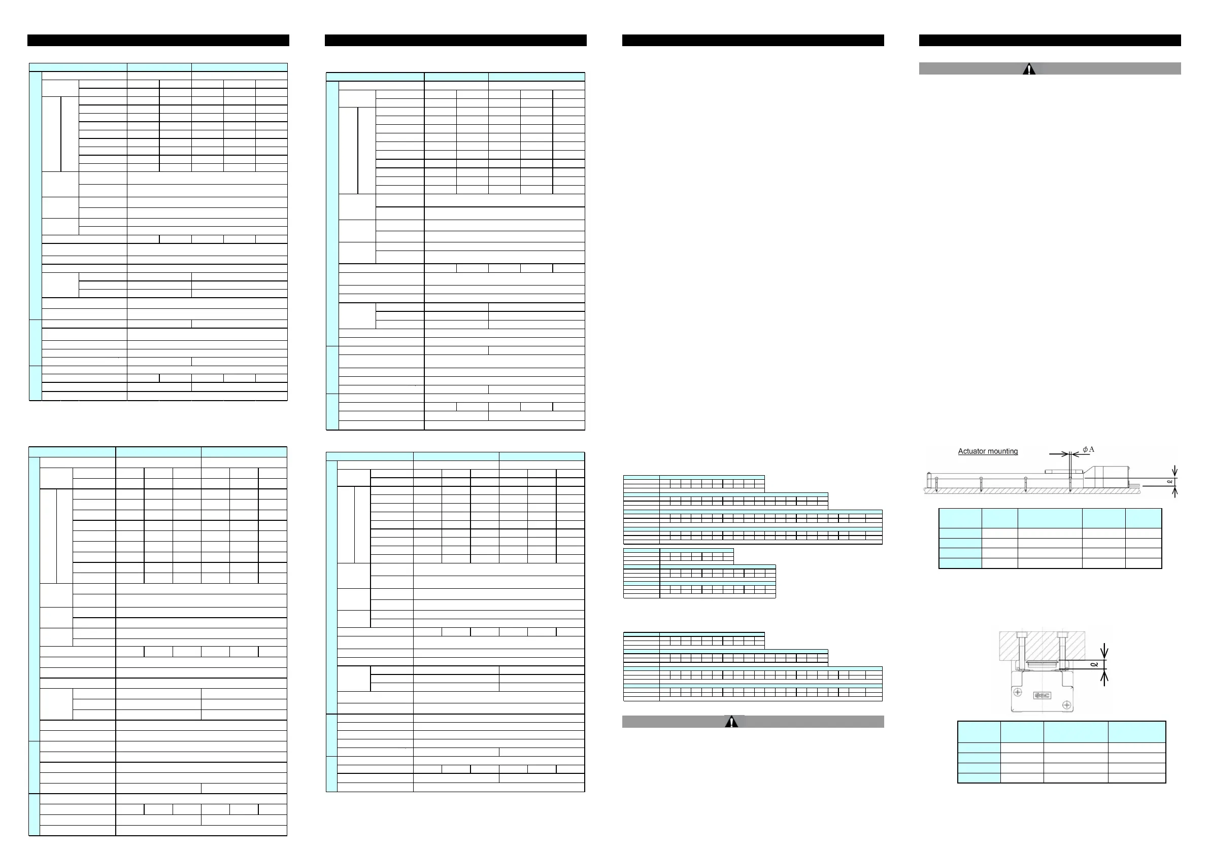
3 Installation
3.1 Installation
Warning
• Do not install the product unless the safety instructions have been read
and understood.
• Do not use the product in excess of its allowable specification.
• When installing, inspecting or performing maintenance on the product,
be sure to turn off the power supplies. Then, lock it so it cannot be
tampered with while work is happening.
Keep the flatness of the mounting surface to 0.1 mm maximum per
500mm. Insufficient flatness of a work piece or actuator mounting
surface can cause play in the guide and increased sliding resistance.
In the case of overhang mounting (including cantilever), use a support
plate or support guide to avoid deflection of the actuator body.
• When mounting the actuator, use all mounting holes.
If all mounting holes are not used, this will not maintain the specified
performance. e.g. the amount of displacement of the table will increase.
• When mounting the actuator leave a space of 40 mm or more to allow
for bending of the actuator cable.
• When mounting the actuator, use screws with adequate length and
tighten them with adequate torque.
Tightening the screws with a torque higher than recommended may
cause malfunction, whilst tightening with a torque lower than
recommended can cause displacement of the mounting position, or the
actuator could become detached from its mounting position.
Model
Screw
size
Max. tightening
torque [N
・
m]
∅
A [mm]
L [mm]
LEF
□
16
M3 0.6 3.5 20
LEF
□
25
M4 1.5 4.5 24
LEF
□
32
M5 3.0 5.5 30
LEF
□
40
M6 5.2 6.6 31
Work piece Mounting
• In order to prevent the work piece fixing screws from damaging the
table, use screws at least 0.5 mm shorter than the maximum thread
depth. Longer screws can hit the body and cause operation failure.
Actuator Mounting
Model
Screw
size
Max. tightening
torque [N
・
m]
L Max. thread
depth[mm]
LEF
□
16
M4 x 0.7 1.5 6
LEF
□
25
M5 x 0.8 3.0 8
LEF
□
32
M6 x 1.0 5.2 9
LEF
□
40
M8 x 1.25 12.5 14
Horizontal 14 20 16 28 * 40
Vertical 3 6 3 7.5 15
Up to 400 10 to 800 5 to 400 20 to 1500 12 to 900 6 to 500
401 to 500 10 to 700 5 to 360 20 to 1100 12 to 750 6 to 400
501 to 600 - - 20 to 900 12 to 540 6 to 270
601 to 700 - - 20 to 630 12 to 420 6 to 230
701 to 800 - - 20 to 550 12 to 330 6 to 180
801 to 900 - - - - -
901 to 1000 - - - - -
1001 to 1100 - - - - -
1101 to 1200 - - - - -
Horizontal
Vertical
Basic type
High precision
Basic type
High precision
10 5 20 12 6
Mep(Pitching)
Mey(Yawing)
Mer(Rolling)
20 39 47 78 157
Rated Voltage [V]
Actuator specificationsElectrical
allowable
moment
note5)
10
10
20
Max. 102
Motor size
0.1 or less
0.05 or less
50 / 20
Motor type
Encoder
□28
Max. 132
Lock nut
Type
note7)
Holding force [N]
Power consumption [W]
note8)
2.9
Non magnetizing lock
5
Rated voltage [V] 24VDC ±10%
□42
Ball screw
Linear guide
5 to 40
90 or less(No condensation)
Step motor(Servo 24VDC)
24VDC ±10%
Incremental
acceleration/
deceleration
2
10000
5000
±0.02
±0.015(Lead H:±0.02)
Operating temperature range
27
27
52
Lead [mm]
Impact/Vibration resistance
[m/s
2
]
note4)
Actuation type
Model LEFS16 LEFS25
Stroke [mm]
note1)
50 to 500 50 to 800
Guide type
Positioning
repeatability
[mm]
Lost motion
[mm]
note3)
Work load
[kg]
note9)
Speed
[mm/s
]
Strok
e
range
Horizontal 40 50 68 26 60 * 75
Vertical 4 12 18 4.5 4.5 25
Up to 400 24 to 1300 16 to 1000 8 to 520 30 to 1200 20 to 1000 10 to 500
401 to 500 24 to 1300 16 to 950 8 to 520 30 to 1200 20 to 1000 10 to 500
501 to 600 24 to 1200 16 to 800 8 to 400 30 to 1200 20 to 1000 10 to 500
601 to 700 24 to 930 16 to 620 8 to 310 30 to 1200 20 to 900 10 to 440
701 to 800 24 to 750 16 to 500 8 to 250 30 to 1140 20 to 760 10 to 350
801 to 900 24 to 610 16 to 410 8 to 200 30 to 930 20 to 620 10 to 280
901 to 1000 24 to 500 16 to 340 8 to 170 30 to 780 20 to 520 10 to 250
1001 to 1100 - - - 30 to 660 20 to 440 10 to 220
1101 to 1200 - - - 30 to 570 20 to 380 10 to 190
Horizontal
Vertical
Basic type
High precision
Basic type
High precision
24 16 8 30 20 10
Mep(Pitching)
Mey(Yawing)
Mer(Rolling)
72 108 216 75 113 225
Step motor(Servo 24VDC)
46
46
101
110
110
207
Ball screw
Linear guide
5 to 40
90 or less(No condensation)
□56.4
±0.02
±0.015(Lead H:±0.02)
0.1 or less
0.05 or less
50 / 20
24VDC ±10%
Lock nut
Type
note7)
Holding force [N]
Power consumption [W]
note8)
5 5
Rated voltage [V]
Non magnetizing lock
Guide type
Actuator specifications
note8)
Max. 158 Max. 202
Strok
e
range
Rated Voltage [V]
Operating temperature range
[
℃
]
[%RH]
Motor size
Motor type
Encoder Incremental
24VDC ±10%
10000
5000
Electrical
LEFS32 LEFS40
Stroke [mm]
note1)
Lead [mm]
Impact/Vibration resistance
2
note4)
Positioning
repeatability
[mm]
Lost motion
[mm]
note3)
50 to 1000 150 to 1200
Work load
[kg]
note9)
Speed
[mm/s
]
Static
allowable
moment
[Nm]
note5)
Max.
acceleration/
deceleration
[mm/s
2
]
Model
Actuation type
Model
Stroke(mm)
50 100 150 200 250 300 350 400 450 500
Weight(kg)
0.83 0.9 0.98 1.05 1 .13 1.2 1.28 1.35 1.43 1.5
Additional w eight for lock(kg)
Model
Stroke(mm)
50 100 150 200 250 300 350 400 450 500 550 600 650 700 750 800
Weight(kg)
1.70 1.84 1.98 2.12 2.26 2.40 2.54 2.68 2.82 2.96 3.10 3.24 3.38 3.52 3.66 3.80
Additional w eight for lock(kg)
Model
Stroke(mm)
50 100 150 200 250 300 350 400 450 500 550 600 650 700 750 800 850 900 950 1000
Weight(kg)
3.15 3.35 3.55 3.75 3.95 4.15 4.35 4.55 4.75 4.95 5.15 5.35 5.55 5.75 5.95 6.15 6.35 6.55 6.75 6.95
Additional w eight for lock(kg)
Model
Stroke(mm)
150 200 250 300 350 400 450 500 550 600 650 700 750 800 850 900 950 1000 1100 1200
Weight(kg)
5.37 5.65 5.93 6.21 6.49 6.77 7.15 7.33 7.61 7.89 8.17 8.45 8.73 9.01 9.29 9.57 9.85 10.13 10.69 11.25
Additional w eight for lock(kg)
LEFS40
0.53
LEFS16
0.12
LEFS32
0.53
LEFS25
0.26
Model
Stroke(mm) 300 500 600 700 800 900 1000
Weight(kg) 1.19 1.45 1.58 1.71 1.84 1.97 2.10
Additional weight for loc k(kg)
Model
Stroke(mm) 300 500 600 700 800 900 1000 120 0 1500 1800 2000
Weight(kg) 2.39 2.85 3.08 3.31 3.54 3.77 4.00 4.46 5.15 5.84 6.30
Additional weight for loc k(kg)
Model
Stroke(mm) 300 500 600 700 800 900 1000 120 0 1500 1800 2000
Weight(kg) 4.12 4.80 5.14 5.48 5.82 6.16 6.50 7.18 8.20 9.22 9.90
Additional weight for loc k(kg)
LEFB16
0.12
LEFB25
0.26
LEFB32
0.53
Model
Stroke(mm)
50 100 150 200 250 300 350 400 450 500
Weight(kg)
0.85 0.92 1 1.07 1.15 1.22 1.3 1.37 1.45 1.52
Additional w eight for lock(kg)
Model
Stroke(mm)
50 100 150 200 250 300 350 400 450 500 550 600 650 700 750 800
Weight(kg)
1.70 1.84 1.98 2.12 2.26 2.40 2.54 2.68 2.82 2.96 3.10 3.24 3.38 3.52 3.66 3.80
Additional w eight for lock(kg)
Model
Stroke(mm)
50 100 150 200 250 300 350 400 450 500 550 600 650 700 750 800 850 900 950 1000
Weight(kg)
3.15 3.35 3.55 3.75 3.95 4.15 4.35 4.55 4.75 4.95 5.15 5.35 5.55 5.75 5.95 6.15 6.35 6.55 6.75 6.95
Additional w eight for lock(kg)
Model
Stroke(mm)
150 200 250 3 00 350 400 450 500 550 600 650 700 750 8 00 850 900 950 1000 1100 1200
Weight(kg)
5.37 5.65 5.93 6.21 6.49 6.77 7.15 7.33 7.61 7.89 8.17 8.45 8.73 9.01 9.29 9.57 9.85 10.13 1 0.69 11.25
Additional w eight for lock(kg)
LEFS40
0.53
LEFS16
0.12
LEFS25
0.26
LEFS32
0.53
Horizontal 6 15 15 28 40
Vertical 3 6 3 7.5 15
Up to 400 10 to 800 5 to 400 20 to 1500 12 to 900 6 to 500
401 to 450 10 to 700 5 to 360 20 to 1100 12 to 750 6 to 400
451 to 500 10 to 600 5 to 300 20 to 1100 12 to 750 6 to 400
501 to 600 - - 20 to 900 12 to 540 6 to 270
601 to 700 - - 20 to 630 12 to 420 6 to 230
701 to 800 - - 20 to 550 12 to 330 6 to 180
801 to 900 - - - - -
901 to 1000 - - - - -
1001 to 1100 - - - - -
1101 to 1200 - - - - -
Horizontal
Vertical
Basic type
Basic type
High precision
type
10 5 20 12 6
Mep(Pitching)
Mey(Yawing)
Mer(Rolling)
20 39 47 78 157
Rated Voltage [V]
Actuator specificationsElectrical
allowable
moment
note5)
10
10
20
note8)
Max. 116
Motor size
0.1 or less
0.05 or less
50 / 20
Motor type
Encoder
□28
Max. 126
Lock nut
Type
note7)
Holding force [N]
Power consumption [W]
note8)
2.9
Non magnetizing lock
5
Rated voltage [V] 24VDC ±10%
□42
Ball screw(LEFS
□
), Ball screw+Belt(LEFS
□
L/R)
Linear guide
5 to 40
90 or less(No condensation)
Battery-less absolute(Step 24VDC)
24VDC ±10%
Battery-less absolute
acceleration/
deceleration
2
10000
5000
±0.02
±0.015(Lead H:±0.02)
Operating temperature range
27
27
52
Lead [mm]
Impact/Vibration resistance
[m/s
2
]
note4)
Actuation type
Model LEFS16 LEFS25
Stroke [mm]
note1)
50 to 500 50 to 800
Guide type
Positioning
repeatability
[mm]
Lost motion
[mm]
note3)
Work load
[kg]
note9)
Speed
[mm/s
]
Strok
e
range
Horizontal 40 50 68 26 60 75
Vertical 4 10 18 4.5 4.5 25
Up to 400 24 to 1300 16 to 1000 8 to 500 30 to 1200 20 to 1000 10 to 500
401 to 500 24 to 1300 16 to 950 8 to 500 30 to 1200 20 to 1000 10 to 500
501 to 600 24 to 1200 16 to 800 8 to 400 30 to 1200 20 to 1000 10 to 500
601 to 700 24 to 930 16 to 620 8 to 310 30 to 1200 20 to 900 10 to 440
701 to 800 24 to 750 16 to 500 8 to 250 30 to 1140 20 to 760 10 to 350
801 to 900 24 to 610 16 to 410 8 to 200 30 to 930 20 to 620 10 to 280
901 to 1000 24 to 500 16 to 340 8 to 170 30 to 780 20 to 520 10 to 250
1001 to 1100 - - - 30 to 660 20 to 440 10 to 220
1101 to 1200 - - - 30 to 570 20 to 380 10 to 190
Horizontal
Vertical
Basic type
High precision
Basic type
High precision
24 16 8 30 20 10
Mep(Pitching)
Mey(Yawing)
Mer(Rolling)
72 108 216 75 113 245
Electrical
LEFS32 LEFS40
Stroke [mm]
note1)
Lead [mm]
Impact/Vibration resistance
[m/s
2
]
note4)
Positioning
repeatability
[mm]
Lost motion
[mm]
note3)
50 to 1000 150 to 1200
Work load
[kg]
note9)
Speed
[mm/s
]
allowable
moment
note5)
acceleration/
deceleration
2
Model
Actuation type
Guide type
Actuator specifications
Max. 222 Max. 222
Strok
e
range
Rated Voltage [V]
Operating temperature range
Motor size
Motor type
Encoder Battery-less absolute
24VDC ±10%
10000
5000
24VDC ±10%
Lock nut
Type
note7)
Holding force [N]
Power consumption [W]
note8)
5 5
Rated voltage [V]
Non magnetizing lock
±0.02
±0.015(Lead H:±0.02)
0.1 or less
0.05 or less
50 / 20
Ball screw(LEFS
□
), Ball screw+Belt(LEFS
□
L/R)
Linear guide
5 to 40
90 or less(No condensation)
□56.4
Battery-less absolute(Step 24VDC)
46
46
101
110
110
207
 Loading...


