LEF#-TF2Y013EN-A
Page 3 of 3
3 Installation (continued)
3.2 Environment
Warning
• Do not use in an environment where corrosive gases, chemicals, salt
water or steam are present.
• Do not use in an explosive atmosphere.
• Do not expose to direct sunlight. Use a suitable protective cover.
• Do not install in a location subject to vibration or impact in excess of
the product’s specifications.
• Do not mount in a location exposed to radiant heat that would result in
temperatures in excess of the product’s specifications.
• Prevent foreign particles from entering the product.
3.3 Mounting
Warning
• Observe the required tightening torque for screws.
Unless stated otherwise, tighten the screws to the recommended
torque for mounting the product.
• Do not make any alterations to the product.
Alterations made to this product may lead to a loss of durability and
damage to the product, which can lead to injury and damage to other
equipment and machinery.
Do not scratch or dent the sliding parts of the table or mounting face
etc., by striking or holding them with other objects. The components
are manufactured to precise tolerances, so that even a slight
deformation may cause faulty operation or seizure.
• Do not use the product until it has been verified that the equipment can
be operated correctly.
After mounting or repair, connect the power supply to the product and
perform appropriate functional inspections to check it is mounted
correctly.
• Do not use the product until it has been verified that the equipment can
be operated correctly.
• After mounting or repair, connect the power supply to the product and
perform appropriate functional inspections to check it is mounted
correctly.
• Allow sufficient space for maintenance and inspection.
3.4 Lubrication
Caution
• SMC products have been lubricated for life at manufacture, and do not
require lubrication in service.
• If a lubricant is used in the system, refer to catalogue for details.
• The recommended grease is lithium grade No.2
Ball screw
Guide
GR-S-010 10
GR-S-020 20
• For standard products which include a prefix of “25A-”,the
recommended grease is the low condensation grease.
Ball screw
Guide
GR-D-010 10
3 Installation (continued)
3.5 Wirng
Warning
• Adjustment, mounting or wiring changes should not be carried out
before disconnecting the power supply to the product.
Electric shock, malfunction and damage can result.
• Do not disassemble the cables.
• Use only specified cables.
Use only specified cables otherwise there may be risk of fire and
damage.
• Do not connect or disconnect the wires, cables and connectors when
the power is turned on.
Caution
• Wire the connector correctly and securely.
Check the connector for polarity and do not apply any voltage to the
terminals other than those specified in the Operation Manual.
• Take appropriate measures against noise.
Noise in a signal line may cause malfunction. As a countermeasure
separate the high voltage and low voltage cables, and shorten the
wiring lengths, etc.
• Do not route input/output wires and cables together with power or high
voltage cables.
The product can malfunction due to noise interference and surge
voltage from power and high voltage cables close to the signal line.
Route the wires of the product separately from power or high voltage
cables.
• Take care that actuator movement does not catch cables.
• Operate with all wires and cables secured.
• Avoid bending cables at sharp angles where they enter the product.
• Avoid twisting, folding, rotating or applying an external force to the
cable.
Risk of electric shock, wire breakage, contact failure and loss of control
of the product can result.
• Select “Robotic cables” in applications where cables are moving
repeatedly (encoder/ motor/ lock).
Refer to the relevant operation manual for the bending life of the cable.
• Confirm correct insulation.
Poor insulation of wires, cables, connectors, terminals etc. can cause
interference with other circuits. Also there is the possibility that
excessive voltage or current may be applied to the product causing
damage.
• Refer to the auto switch references in “Best Pneumatics“ when an auto
switch is to be used
3.6 Actuator Ground connection
• The Actuator must be connected to ground to shield the actuator from
electrical noise. The screw and cable with crimping terminal and
toothed washer should be prepared separately by the user.
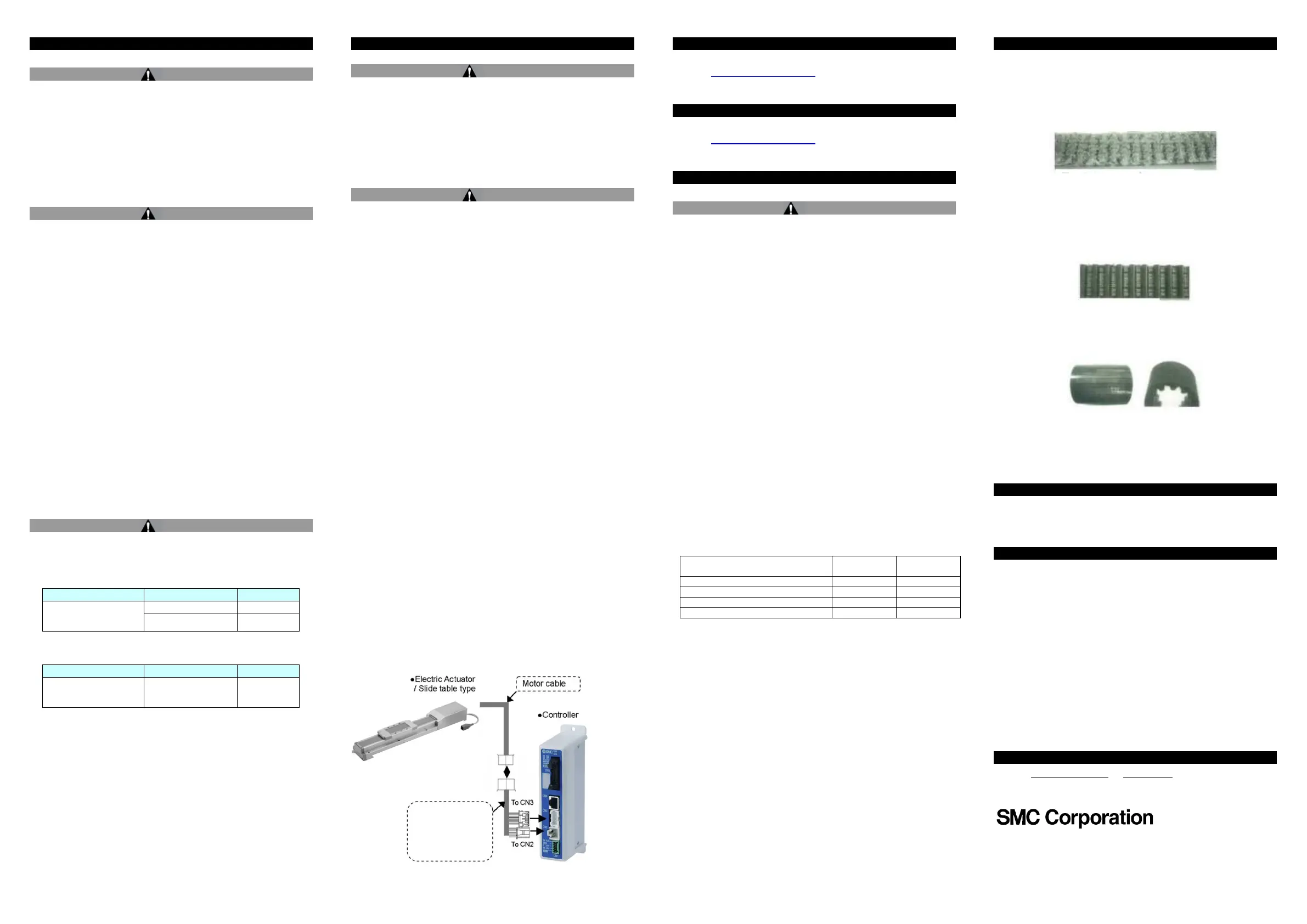
Wiring of Actuator to Controller
4 How to Order
• For standard products, refer to the catalogue on the SMC website
(URL: https://www.smcworld.com) for the how to order information.
5 Outline Dimensions
• For standard products, refer to the catalogue on the SMC website
(URL: https://www.smcworld.com) for outline dimensions.
6 Maintenance
6.1 General Maintenance
Caution
• Not following proper maintenance procedures could cause the product
to malfunction and lead to equipment damage.
• If handled improperly electricity and compressed air can be dangerous.
• Maintenance of electromechanical and pneumatic systems should be
performed only by qualified personnel.
• Before performing maintenance, turn off the power supply and be sure
to cut off the supply pressure. Confirm that the power has been
discharged and the air is released to atmosphere.
• After installation and maintenance, apply operating pressure and
power to the equipment and perform appropriate functional and
leakage tests to make sure the equipment is installed correctly.
• If any electrical or pneumatic connections are disturbed during
maintenance, ensure they are reconnected correctly and safety checks
are carried out as required to ensure continued compliance with
applicable national regulations.
• Do not make any modification to the product.
• Do not disassemble the product, unless required by installation or
maintenance instructions.
• Incorrect handling can cause an injury, damage or malfunction of the
equipment and machinery, so ensure that the procedure for the task is
followed.
• Always allow sufficient space around the product to complete any
maintenance and inspection.
6.2 Periodical Maintenance
• Maintenance should be performed according to the table below:
Belt Check
Inspection before daily operation
Inspection every six months*
Inspection every 1000 km*
Inspection every 5 million cycles*
*whichever of these occurs first.
• Following any maintenance, always perform a system check. Do not
use the product if any error occurs, as safety cannot be assured if
caused by any un-intentional malfunction.
6.3 Appearance Check
• The following items should be visually monitored to ensure that the
actuator remains in good condition and there are no concerns flagged;
・Loose Screws,
・Abnormal level of dust or dirt,
・Visual flaws / faults,
・Cable connections,
・Abnormal noises or vibrations.
6 Maintenance (continued)
6.4 Belt Check
• If one of the 6 conditions below are seen, do not continue operating
the actuator, contact SMC immediately.
・
Tooth shaped canvas is worn out.
Canvas fibre becomes “fuzzy”, rubber is removed, and the fibre gains
a white colour. The lines of fibre become very unclear.
・
Peeling off or wearing of the side of the belt.
The corner of the belt becomes round and frayed, with threads
beginning to stick out.
・
Belt is partially cut.
Belt is partially cut. Foreign matter could be caught in the teeth and
cause flaws.
・
Vertical line of belt teeth.
Flaw which is made when the belt runs on the flange.
・
Rubber back of the belt is softened and sticky.
・
Crack on the back of the belt.
7 Limitations of Use
7.1 Limited warranty and disclaimer/compliance requirements
• Refer to Handling Precautions for SMC Products.
8 Product disposal
This product should not be disposed of as municipal waste. Check your
local regulations and guidelines to dispose of this product correctly, in
order to reduce the impact on human health and the environment.
9 Contacts
Refer to www.smcworld.com or www.smc.eu for your local distributor /
importer.
'SMC Corporation, 4-14-1, Sotokanda, Chiyoda-ku, Tokyo 101-0021, Japan
Specifications are subject to change without prior notice from the manufacturer.
© 2021 SMC Corporation All Rights Reserved.
Template DKP50047-F-085M
LE-CP-*-*
(no lock or sensor)
LE-CP-*-B-*
(with lock and sensor)
 Loading...


