USER’S MANUAL
18
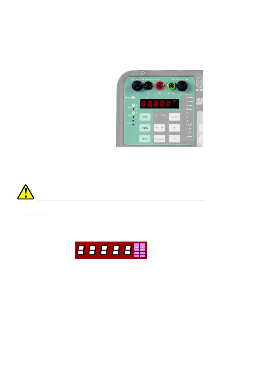
TIMER SECTION
The PTE-100-C PRO’s digital Timer display is located on the left hand sec-
tion of the front panel, along with its control buttons and status LEDs.
Monitor Inputs
Tested relay’s operation is detected
by means of two inputs:
1.
dry (non-energized) contact
monitoring, and
2. A BLACK/RED input for
vol
250 Vac/dc maximum.
Both inputs are protected by 0.1 A FAST type 5x20 mm. fuses. Press and
turn the fuse holder 90º counter clockwise to replace a blown fuse.
REPLACE BLOWN FUSES WITH IDENTICAL ONES ONLY. DAMAGE
RESULTING FROM INCORRECT FUSE REPLACEMENT IS NOT COVERED
BY THE WARRANTY
Time Display
Time values resulting from tests are shown in Display #1 with a maximum
resolution of 1 millisecond.
Display #1 is a multi-function display. Besides time values in seconds or
cycles of the AC supply line, it can show various measurement units that are
automatically labeled at its right hand edge:

 Loading...
