Features 2
Dual 3-port valves, 4 positions
VQC1000/2000 (Rubber seal type only)
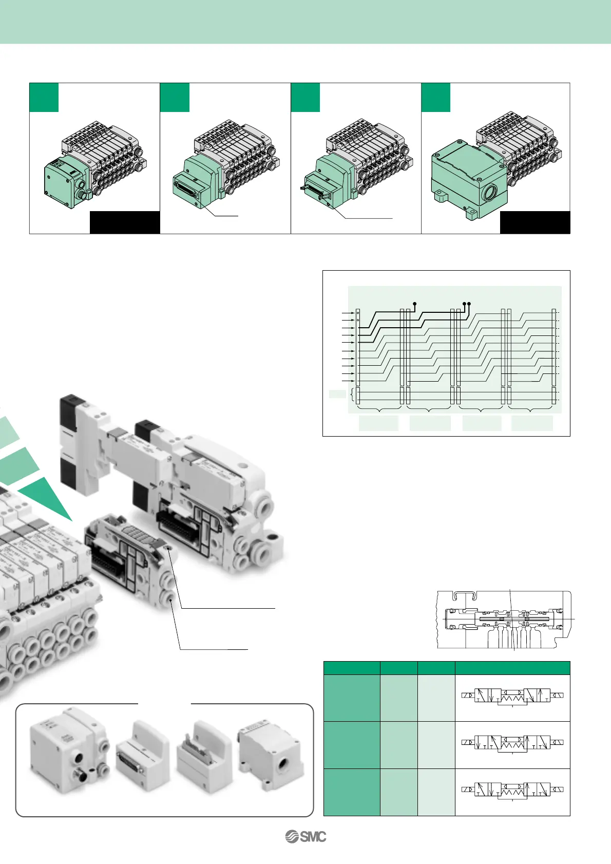
A wide variety of prepackaged wiring configurations
R1 A P B R2
VQC1A01
VQC2A01
VQC1B01
VQC2B01
VQC1C01
VQC2C01
N.C.
valve
N.C.
valve
N.O.
valve
N.O.
valve
N.C.
valve
N.O.
valve
Model
A side
B side
JIS symbol
1
(P)
5
(R1)
3
(R2)
4
(A)
2
(B)
1
(P)
5
(R1)
3
(R2)
4
(A)
2
(B)
1
(P)
5
(R1)
3
(R2)
4
(A)
2
(B)
S
Kit
(Serial transmission)
F
Kit
(D-sub connector)
Protective enclosure
conforms to IP 67
T
Kit
(Terminal block box)
P
Kit
(Flat ribbon cable)
• Our four standard wiring packages bring a world of ease to wiring and maintenance work, while the protective enclosures of two of
them conform to IP67 standards.
• The S Kit is compatible with a combined I/O unit.
(If used with gataway unit, SI must be output only.)
Replaceable
One-touch fittings
Single mounting screw,
clamp construction
NEW CONCEPT
(Refer to the connector wiring diagram)
Printed circuit board patterns between connectors are shifted at every station.
This allows for viable connections to take place without necessarily specifying
whether the manifold station is double, single, or mixed wiring.
Series
EX500
25-pin
26-pin, 20-pin
Connector wiring diagram (mixed wiring)
1
2
3
4
5
6
7
8
9
10
5
6
7
8
9
10
1
2
3
4
5
6
7
8
9
10
19
20
19
20
6
A
4
A
3
A
1
A
5
B
2
B
Output
COM
Station 1
Double wiring
Station 2
Single wiring
Station 3
Double wiring
Station 4
Single wiring
1
2
3
4
Protective enclosure
conforms to IP 67
Connector type manifold
• The use of multi-pin connectors to replace wiring inside manifold
blocks provides flexibility when adding stations or changing
manifold configuration.
• Connector clusters give a new dimension to the notion of
interchangeability. For example, changing from F Kit (D-sub
connector) to S Kit (serial transmission) is achieved by simply
changing the kit piece.
• Two 3-port valves built into one body.
• The 3-port valves on the A and B sides can operate
independently.
• When used as 3-port valves, only half the number of
stations is required.
• Can also be used as a 4-position, 5-port type valve.
Exhaust center : VQC1A01
VQC2A01
Pressure center: VQC1B01
VQC2B01
Serial transmission
EX500
D-sub connector
Flat ribbon cable
Terminal block box
Wiring
1
2
3
4
5
6
7
8
9
10
19
20
1
2
3
4
5
6
7
8
9
10
19
20
1
2
3
4
5
6
7
8
9
10
19
20
1
2
3
4
5
6
7
8
9
10
19
20
1
2
3
4
5
6
7
8
9
10
19
20
1
2
3
4
5
6
7
8
9
10
19
20
 Loading...


