Do you have a question about the Sony DSR-PD190P and is the answer not in the manual?
Details about the camcorder's system, video signal, usable cassette, tape speed, and recording times.
Specifications of the AC adaptor, including power requirements, dimensions, and operating temperature.
Specifications for the rechargeable battery pack, including voltage, capacity, dimensions, and type.
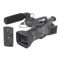
Specifications for the wide conversion lens, including its power, structure, and dimensions.
Guidelines for handling flat cables, flexible boards, and connectors during repairs to prevent damage.
Methods to prevent power shut-off during repairs, involving remote commander or DC IN terminal.
Explains the self-diagnosis display and function, including error codes and their meanings.
Procedure for removing the LCD panel, PD-217 boards, and inverter transformer unit.
Procedure for removing the EVF section, including the LB-100D board and associated components.
Procedure for removing the upper handle block assembly, including the microphone holder.
High-level overview of the camcorder's functional blocks and their interconnections.
Diagram illustrating the power supply distribution and regulation within the camcorder.
Diagram showing the physical layout and connections of major internal boards.
Detailed circuit schematics for various boards like CD-512, JK-267, CK-140, etc.
Diagrams illustrating component layout for various boards like CD-512, JK-267, CK-140, etc.
Visual breakdown of camcorder sections with numbered parts for identification and replacement.
Exploded view of the camcorder's overall section 1, showing parts like handle and cabinet assemblies.
Exploded view of the battery panel section, showing components like MK-016 and KP-013 boards.
Detailed procedures for adjusting camera functions like white balance, gain, and iris.
Procedures for adjusting the viewfinder's VCO, brightness, contrast, and white balance.
Procedures for adjusting the LCD system's VCO, brightness, black limit, and white balance.