Movies recorded with 24-bit audio may not be played back normally on devices or software incompatible with 24-bit
audio, resulting in unexpectedly loud volumes or no sound.
If your camera is not compatible with the digital audio interface of the Multi Interface Shoe, set the switch to
“ANALOG.”
When the message “This accessory is not supported by the device and cannot be used.” is displayed on the
camera, set the switch to “ANALOG.”
If this does not help, see here.
When a TRS audio cable with the 3.5 mm diameter plug (commercially available) is connected, the receiver
outputs analog signals via the cable.
When a device with a USB audio input capability is connected, the receiver outputs digital signals.
When you do not intend to use the receiver, set the switch to “OFF” to conserve the battery power.
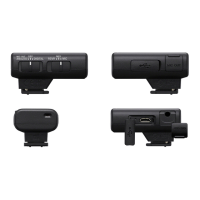
Mode switch (SEP/MIX) (ECM-W3)
By selecting a receiver mode with this switch before you start video recording with the camera, you can make
recordings with audio from either of the two microphones individually as the left or right channel audio; or recordings
with mixed audio from the two microphones.
2.
Multi Interface foot3.
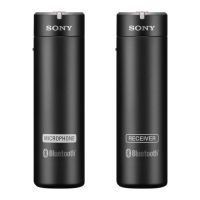
LINK (LINK1/LINK2) lamp (ECM-W3)
LINK lamp (ECM-W3S)
Indicates the connection state between the receiver and the microphone.
Hint
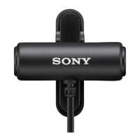
On the nameplate under the clip of the microphone, you will find either the number “1” or “2” indicated for microphone
identification. The number “1” indicates the microphone No. 1; and the number “2” indicates the microphone No. 2. To identify
which microphone connection is active with the receiver, check the state of the LINK1 lamp for the microphone No. 1 and the
LINK2 lamp for the microphone No. 2 on the receiver. (Applicable to ECM-W3)
4.
Power lamp (Green: Powered, Orange: Charging the battery)
Indicates the power state of the receiver or the battery charge state.
When the power lamp stays blinking in orange, battery charging is needed.
5.
Charging connector
Supplies power to the receiver for battery charging via the charging case.
6.
SAFETY lamp
Lights in yellow when the receiver goes into SAFETY mode and goes out when the receiver comes out of the mode.
7.
SAFETY button
Pressing and holding the SAFETY button for about 2 seconds places the receiver into SAFETY mode.
For details, see About the SAFETY button.
8.
USB Type-C® port
Connect to a power source with a USB Type-C cable (commercially available) for charging the built-in battery of the
receiver and/or for supplying power to the receiver.
This port can be connected to a device with a USB audio input capability, such as a computer or a smartphone, for
audio recording as well.
9.
Microphone out jack
Connect to the microphone in jack on the camera with a TRS audio cable with the 3.5 mm diameter plug
(commercially available) for audio recording.
10.
Connector Protect Holder/Stand
Attached to the receiver at the time of purchase.
11.
 Loading...