HCD-EX6/EX6T/EX8/EX8T/EX9/EX9T
5
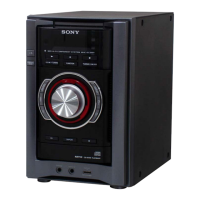
CAPACITOR DISCHARGE FOR ELECTRIC SHOCK PREVENTION
PT-POWER board
PT-POWER board
C013 C014
(Right side view)
In checking the PT-POWER board, make a capacitor discharge
of C013 and C014 for electric shock prevention.
00 ȍW 00 ȍW
Note: Please take out the side panel (R) from a set refer to DISASSEMBLY (page 7).
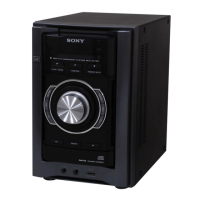
PRECAUTION WHEN INSTALLING A NEW OP UNIT/
PRECAUTION BEFORE UNSOLDERING THE STATIC
ELECTRICITY PREVENTION SOLDER BRIDGE
When installing a new OP unit, be sure to connect the fl exible
printed circuit board fi rst of all before removing the static electric-
ity prevention solder bridge by unsoldering.
Remove the static electricity prevention solder bridge by unsolder-
ing after the fl exible printed circuit board has already been con-
nected.
(Do not remove nor unsolder the solder bridge as long as the OP
unit is kept standalone.)
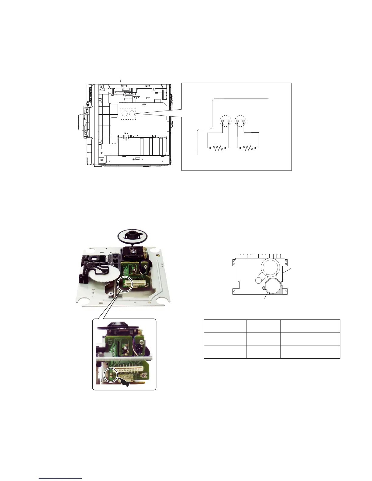
HOW TO DISTINGUISH TAPE MECHANISM DECK
(HCD-EX6T/EX8T/EX9T only)
Two kinds of tape mechanism decks installed by this set exist.
Please do the repair exchange after confi rming which tape mecha-
nism deck set of the repair according to how to distinguish the
fi gure below.
motor
Metal part: TCM-J1
Mold part: CS-21SC-901TP
tape deck
Tape Deck Name
Tape Deck
Part No.
Belt Part No.
TCM-J1 A-1527-851-A
2-670-389-01 BELT (1)
3-214-817-01 BELT (FR)
CS-21SC-901TP 1-797-575-11
2-688-621-01 BELT (R/F)
2-688-622-01 BELT (MAIN)
 Loading...