Do you have a question about the Sony HCD-H12 and is the answer not in the manual?
Details of the CD player section, including system and laser specs.
Technical details for FM and AM tuning, including frequency ranges and antenna terminals.
Power output ratings for the amplifier section, including continuous and peak music power.
Recording system and frequency response for the cassette deck, with Dolby NR status.
Power requirements and consumption for different regions.
Identifies and explains the purpose of all buttons and indicators on the front panel.
Explains the controls and indicators on the remote commander and the unit's display.
Step-by-step guide for removing the main case and loading panel of the unit.
Procedure for removing the front panel assembly and cassette lid mechanism.
Guide for disconnecting and removing the TC mechanism block and main circuit board.
Steps for safely removing the power supply block from the unit.
Procedures and torque specifications for mechanical adjustments like tape tension.
Detailed procedures for electrical adjustments in the deck section, including test tape usage.
Steps to adjust the record/playback head azimuth for optimal tape playback.
Procedure for adjusting tape speed using test tapes and frequency counters.
Steps for setting record bias levels and input levels for optimal tape recording.
Procedure for adjusting playback signal levels for accurate audio reproduction.
Adjustments for FM and AM reception, including signal generator setup.
Adjusting voltage levels and tracking for the SW (Shortwave) circuit.
Procedures for checking S-curve, RF level, and E-F balance for CD playback.
Measuring the free-run frequency of the RF PLL circuit for CD operation.
Advisory note regarding focus/tracking gain adjustment, recommending against it unless critical.
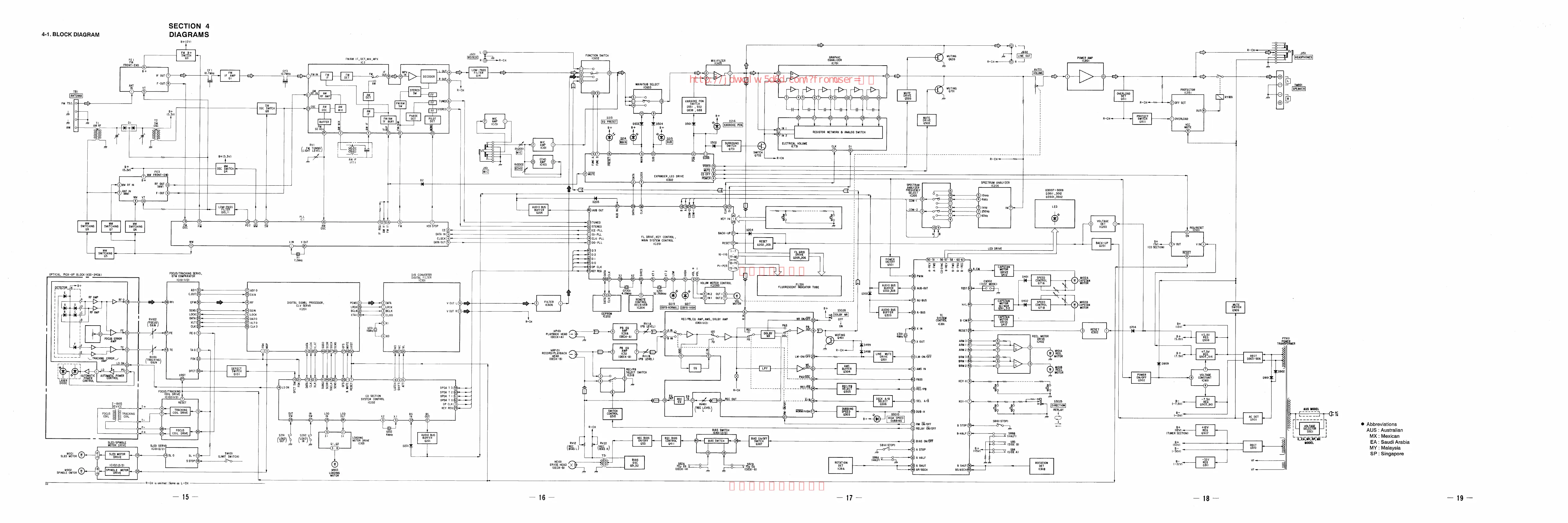
Overview of the main functional blocks and their interconnections within the system.
Visual guide showing the physical placement of various circuit boards within the unit.
Layout of components and traces on the main printed wiring board.
Detailed schematic of the main circuit board, showing component connections and values.
Schematic diagram illustrating the circuitry of the tape deck mechanism.
Layout of components and traces on the printed wiring boards for the deck section.
Layout of components and traces on the printed wiring board for the display unit.
Schematic diagram detailing the circuitry for the unit's display.
Detailed schematic of the CD player section's electronic components and connections.
Diagrams showing the pin configurations and lead orientations of various semiconductor components.
Diagram showing the assembly of the unit's case and power supply components.
Exploded view illustrating the assembly of the front panel and its controls.
Diagram showing the mechanical chassis and components of the tape deck mechanism.
Exploded views illustrating the assembly of the CD mechanism components.
List of all capacitors with part numbers, values, and specifications.
Listing of all connectors used in the system, including pin counts.
Catalog of diodes with part numbers and types.
List of all integrated circuits, including part numbers and functions.
Comprehensive list of resistors with part numbers and values.
Comprehensive list of transistors, including part numbers and characteristics.
List of components specific to the BD(A) board, including ICs, diodes, and resistors.
Listing of components such as capacitors, filters, and connectors for the Main board.
Components list for the power section, including transistors, resistors, and capacitors.