3
Overview
Overview
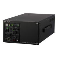
• The HSCU300RF Camera Control Unit connects to a Sony
HSC300RF or HSC100RF HD color camera via an optical
fiber cable. It performs signal processing, provides an
interface for external equipment, and supplies power to the
camera.
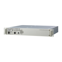
• The HSCU300R Camera Control Unit connects to a Sony
HSC300R or HSC100R HD color camera via a triaxial cable.
It performs signal processing, provides an interface for
external equipment, and supplies power to the camera.
The CCU features a down converter which converts HD
signals
1)
from a camera to SD signals
2)
, and a simplified
return video up converter which converts SD signals to HD
signals.
1) HD (High Definition) signal: Name for 1125/750-line HDTV signals
2) SD (Standard Definition) signal: Name for NTSC/PAL, 525/625
component, and 525/625 composite signals
The CCU can be combined with an RCP-1000-series Remote
Control Panel (optional) to form a camera control system. The
CCU can also be combined with an MSU-1000/1500 Master
Setup Unit (optional), by installing the HZCU-MC3 multi-
camera control system software, to form a multi-camera
application system controlling multiple cameras.
In addition, an HKCU-FP2 CCU Control Panel (optional) can
be mounted on the front panel to form a simple remote control
system.
Features
Multi-system input/output interface
The CCU is equipped with the following input and output signal
connectors as standard equipment.
Video outputs
• SDI (main), 2-system (HD/SD selectable, embedded digital
audio)
• SDI (monitor), 2-system (HD/SD selectable, embedded
digital audio, superimposed character and marker display)
• Analog composite (VBS 2-system, PIX 1-system,
SYNC/WF 1-system)
• Analog component, 1-system (HD Y/Pb/Pr, HD R/G/B, SD
Y/R-Y/B-Y, SD R/G/B 4-format selectable)
• SYNC/WF 1-system (HD/SD selectable)
The analog composite (WF1 system) and SYNC1 system share a
single connector.
Video inputs
• Reference input (HD/SD support)
• SDI return input, 2-system (HD/SD selectable)
• VBS return input, 2-system
• VBS prompter input, 2-system
(HSCU300RF can transfer only one selected VBS prompter
input system to the camera.)
Audio input/outputs
• Microphone (analog) output, 2-system (XLR-3-pin)
• Intercom input/output, 2-system (D-sub 25-pin)
• PGM (program audio) input, 2-system (D-sub 25-pin)
Other input/outputs
• Tally (R/G) (D-sub 25-pin)
• Microphone remote (D-sub 25-pin)
• WF (waveform monitor) remote output (D-sub 25-pin)
• WF (waveform monitor) mode output (D-sub 25-pin)
• Trunk (D-sub 25-pin)
• REMOTE (8-pin)
• LAN (RJ-45, 8-pin)
The WF remote output, WF mode output, trunk, and microphone
remote share a common 25-pin connector.
External sync signals
The CCU can be locked to an external sync signal. Either an
HD tri-level sync signal or an SD sync (black burst) signal can
be used as the sync signal.
Optical digital transmission (HSCU300RF)
HD video signals can be transmitted up to 2 km (1 1/4 miles)
between a camera and the CCU over an optical fiber cable.
Digital Triax Transmission (HSCU300R)
The CCU and camera are connected using the industry-
standard double-shielded triaxial camera cable (commonly
referred to as triax). The camera and CCU are equipped with
the latest Sony-developed digital transmission technology
which can transmit high-resolution pictures between the
camera and CCU.
Built-in down converter
HD signals from the camera can be converted to high-
resolution SD component SDI output signals using the
wideband down converter. The output signal aspect ratio can
be set to 4:3 edge crop, 16:9 squeeze, or letterbox. The down
converted SD signal has independent image enhancement,
gamma, and matrix functions that can be controlled externally.
Built-in simplified up converter
SD signal return video is displayed in the HD viewfinder using
a simple up converter. The return video aspect ratio can be set
to 4:3 edge crop, 16:9 squeeze, or letterbox.
Electric shock prevention
A safety function cuts the high-voltage supply from the CCU if
the connection to the camera becomes unsafe.
When power is applied, low-voltage power is first supplied to
the camera. After the connected camera is correctly identified
using tone signal detection, the regular DC180 V high-voltage
power is supplied to the camera. Power is not supplied to
cameras not connected via a dedicated camera connection
cable.
Alarm indicators are also fitted to indicate cable open-circuit
and short-circuit conditions.
Note
Note
 Loading...