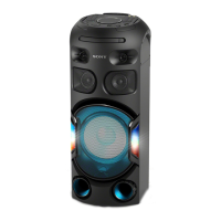
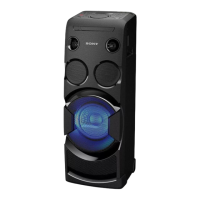
MHC-V50/V50D
3
1. SERVICING NOTES ............................................. 4
2. DISASSEMBLY
2-1. Disassembly Flow ........................................................... 10
2-2. Side (L) Panel, Side (R) Panel ........................................ 11
2-3. Top Panel Section ........................................................... 12
2-4. Loading Panel Assy ........................................................ 13
2-5. CDM Section .................................................................. 14
2-6. Back Panel Section, Module Cover ................................ 15
2-7. DAMP Board .................................................................. 16
2-8. Bracket Chassis ............................................................... 17
2-9. MOTHERBOARD Board ............................................... 18
2-10. SMPS Board ................................................................... 19
2-11. Chassis ............................................................................ 19
2-12. Front Panel Section ......................................................... 20
2-13. Loudspeaker (20CM) ...................................................... 21
2-14. Loudspeaker (8CM) ........................................................ 22
2-15. Service Optical Device (7G), Flexible Flat Cable .......... 23
3. TEST MODE ............................................................ 24
4. ELECTRICAL CHECK ......................................... 25
5. TROUBLESHOOTING .......................................... 26
6. DIAGRAMS ............................................................... 32
6-1. Block Diagram - CD/USB/HDMI Section - ................... 33
6-2. Block Diagram - MAIN Section - ................................... 34
6-3. Block Diagram - DAMP Section - .................................. 35
6-4. Block Diagram - TOUCH/LED DRIVER Section - ....... 36
6-5. Block Diagram
- PANEL/POWER SUPPLY Section - ............................ 37
6-6. Printed Wiring Board - MOTHERBOARD Board - ....... 39
6-7. Printed Wiring Board - DAMP Board - .......................... 40
6-8. Printed Wiring Board - VOLUME Board - ..................... 41
6-9. Schematic Diagram - VOLUME Board (1/2) - ............... 42
6-10. Schematic Diagram - VOLUME Board (2/2) - ............... 43
6-11. Printed Wiring Board - SMPS Board - ........................... 44
6-12. Printed Wiring Board - MIC Board - .............................. 45
6-13. Schematic Diagram - MIC Board - ................................. 45
6-14. Printed Wiring Board - LCD Board - .............................. 46
6-15. Printed Wiring Board
- SENSOR Board (Component Side) - ........................... 47
6-16. Printed Wiring Board
- SENSOR Board (Conductor Side) - ............................. 48
TABLE OF CONTENTS
6-17. Printed Wiring Board - IR Board - .................................. 49
6-18. Schematic Diagram - IR Board - .................................... 49
6-19. Printed Wiring Board
- TOP PARTY LIGHT Board - ....................................... 49
6-20. Schematic Diagram
- TOP PARTY LIGHT Board - ....................................... 49
6-21. Printed Wiring Board
- PARTY LIGHT DRIVER Board - ................................ 50
6-22. Schematic Diagram
- PARTY LIGHT DRIVER Board - ................................ 51
6-23. Printed Wiring Board
- BACK PARTY LIGHT L Board - ................................ 52
6-24. Schematic Diagram
- BACK PARTY LIGHT L Board - ................................ 52
6-25. Printed Wiring Board
- BACK PARTY LIGHT R Board - ................................ 52
6-26. Schematic Diagram
- BACK PARTY LIGHT R Board - ................................ 52
6-27. Printed Wiring Board - SPK RGB L Board - .................. 53
6-28. Schematic Diagram - SPK RGB L Board -..................... 53
6-29. Printed Wiring Board - SPK RGB R Board - ................. 53
6-30. Schematic Diagram - SPK RGB R Board - .................... 53
6-31. Printed Wiring Board - USB Board - .............................. 54
6-32. Schematic Diagram - USB Board - ................................. 54
7. EXPLODED VIEWS
7-1. Side Panel Section .......................................................... 56
7-2. Loading Panel Section .................................................... 57
7-3. Back Panel Section ......................................................... 58
7-4. Top Panel, PARTY LIGHT Board Section-1 .................. 59
7-4. Top Panel, PARTY LIGHT Board Section-2 .................. 60
7-5. MOTHERBOARD Board Section .................................. 61
7-6. Chassis Section ............................................................... 62
7-7. Front Panel Section ......................................................... 63
7-8. Speaker Cabinet Section ................................................. 64
7-9. CDM Section .................................................................. 65
7-10. CD/DVD Mechanism Section
(CDM90-DVBU204//C) ................................................. 66
8. ELECTRICAL PARTS LIST .............................. 67
Accessories are listed in the last part of the electrical parts
list.

 Loading...