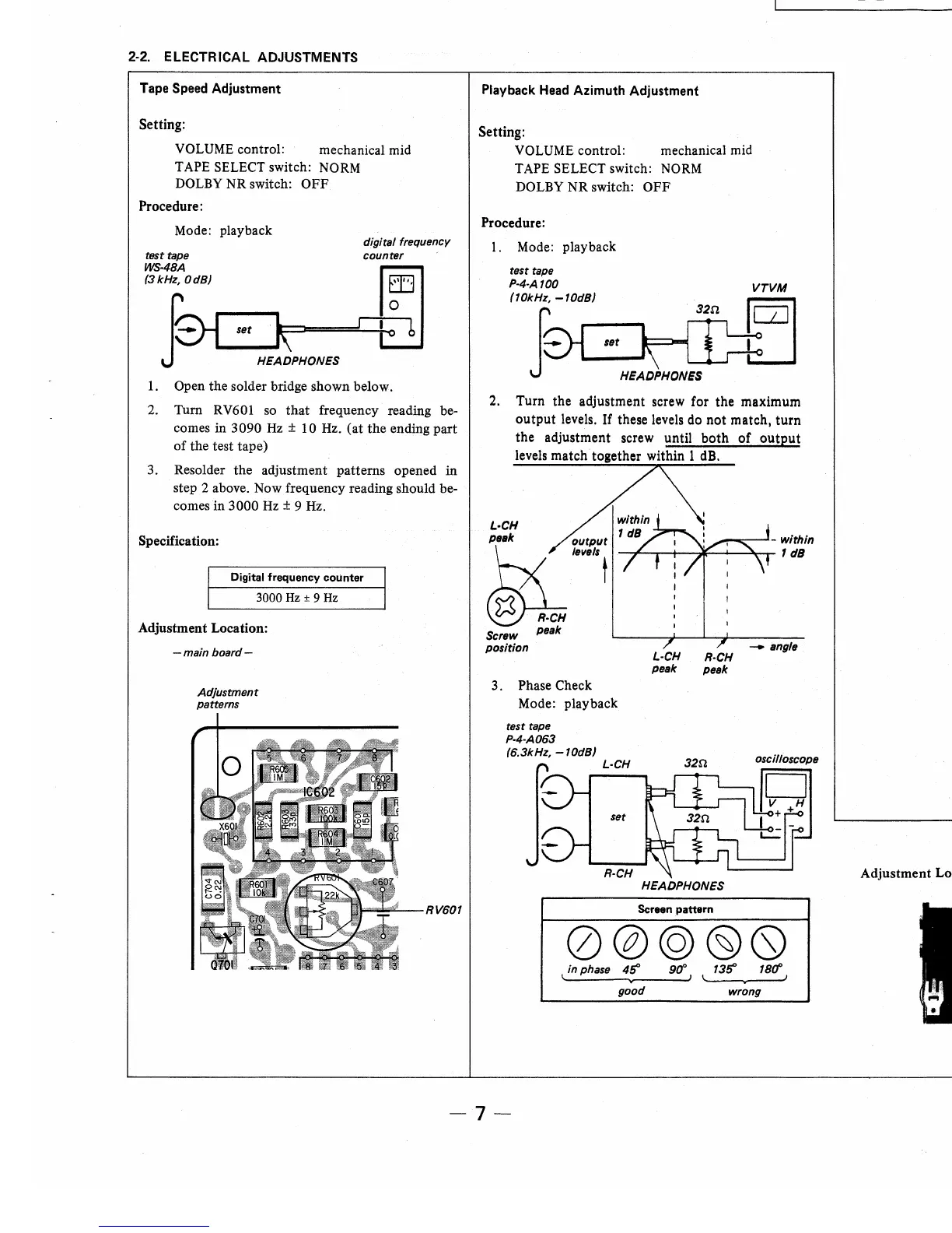
2-2. ELECTRICAL ADJUSTMENTS
Tape
Speed
Adjustment
Setting:
VOLUME control: mechanical mid
TAPE SELECT switch:
NORM
DOLBY
NR switch:
OFF
Procedure:
Mode: playback
digital frequency
test tape
WS-48A
(3kHz, OdB)
counter
set
·k~
~
HEADPHONES
1.
Open the solder bridge shown below.
2.
Turn RV601 so
that
frequency reading be-
comes in
3090Hz±
10Hz.
(at
the
ending
part
of
the test tape)
3. Resolder the adjustment patterns opened
in
step 2 above. Now frequency reading should be-
comes in 3000
Hz
± 9 Hz.
Specification:
Digital
frequency
counter
3000Hz±
9Hz
Adjustment Location:
-main
board-
Adjustment
patterns
RV601
WM-DDm
WM-DDm
Playback Head
Azimuth
Adjustment
Setting:
VOLUME control: mechanical mid
TAPE SELECT switch:
NORM
DOLBY NR switch:
OFF
Procedure:
1.
Mode: playback
32n.
HEADPHONES
VTVM
El
2.
Turn the adjustment screw for the maximum
output
levels.
If
these levels do
not
match,
turn
the adjustment screw until
both
of
output
levels match together within 1 dB.
L·CH
~;
~~:;
@hk
Screw peak
position
3. Phase Check
Mode: playback
test tape
P-4-A063
(6.3kHz,
-10d8)
.-_.----'-within
--::~~-+---:~_...-~or-
1 dB
L·CH
peak
R·CH
peak
-angle
L-CH
320
HEADPHONES
Screen pattern
0@@(§)Q
lin
phase
45'
90°
1
t
135'
18CfJ
~------v----J
good wrong
Adjustment Location:
adjustment screw
-7-
Playback Level
Adjustment
Setting:
VOLUME control: mechanical mid
TAPE SELECT switch:
NORM
DOLBY
NR switch:
OFF
Procedure:
Mode: playback
test
tape
P-4-L300
(315Hz,
OdB)
DOLBY
out
VTVM
(
Refer
to
the
following
figure)
for
DOLBY
out
point.
Specification:
DOLBY
out
level: 0.073 V (
-20.5
± 0.2 dB)
1)
If
necessary, adjust
RV
1 0 1 ( L-CH) and R V20 1
(R-CH) for the specification.
2) Confirm
that
the
output
level
of
DOLBY
out
is
not changed when. repeating playback and
stop .
Adjustment Location:
- main board -
IR26
UI!
RV101
(L-CH)
;.__,_..-..._
RV201
(R-CH)
R-CH
DOLBY
out
-8-
 Loading...