- 20 -
Disconnect the power supply
before attempting any work
on the sensor!
During installation, the elec-
tric power cable to be con-
nected must be dead. There-
fore, sw
itch 'OFF' the power
first and use a voltage tester
to make sure the wiring is off
circuit.
Installing the sensor involves
work on the mains power
supply. This work mus
t there-
fore be carried out profes-
sionally in accordance with
the applicable national wir-
ing regulations and electrical
operating conditions (VDE
0100).
Terminal B 1, B 2 is a switch-
ing c
ontact for low-energy
circuits, no higher than 1 A.
This must be provided with
appropriate fuse protection.
Control output DIM 1-10 V
must only be used for con-
ne
cting electronic ballasts
with electrically isolated
control signal.
System components
Load module
Sensor module
Sensor base
Dip switches
(1) Normal/test mode
(2) Semi-/fully automatic mode
(3) Button/swit ch
(4) 'ON' / 'ON'-'OFF' button
(5) DIM option
Constant lighting control
'ON
'/'OFF'
Twilight setting
Time setting
Switching output 1
HV AC stay-'ON' time
Switching output 2
HV AC switch-'ON' delay
Switching output 2
Reach setting
10.1
Kaiser stud-wall junction box,
optional
10.
2
Clamping-type ceiling adapter ,
optional
Surface-mounting adapter
IP 54, optional
Locking mechanism
Assembly/Installation
Parallel-connected
configurations
Sta
y-'ON' time
Orientation light
DIM option
Assembly/Installation (see chart on page 2)
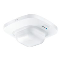
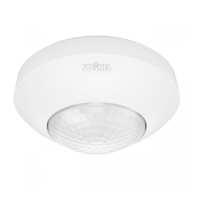
The sensor is only intended for
concealed, indoor installation in
ceilings (apart from the COM 1
AP - surface-mounted - option).
A clamping-type ceiling adapter
or sur
face-mounting adapter is
not included.
Sensor and load module come
ready assembled and must be
plugged together after fitting
the load module and setting the
potentiometers/dip switches.
The sensor module must then
be locked in position at the
catch mechanism , using a
screwdriver if necessary.
Accessories:
Kaiser junction box for stud walls
EAN no.: 4007841 000370
Clamping-type ceiling adapter
EAN no. 4007841 002855
Surface-mounting adapter,
EAN no.: 4007841 000363
Guar d cage,
EAN no.: 4007841 003036
Service remote control,
EAN no.: 4007841 000387
User remote control,
EAN no.: 4007841 003012
Operating instructions
GB
Dear Customer,
Congratulation on purchasing
your new STEINEL sensor and
thank you for the confidence
you have shown in us. You have
chosen a high-quality product
that has been manufact
ured,
tested and packed with the
greatest care.
Please familiarise yourself with
these instructions before
attempting to install the product
because prolonged, reliable a
nd
trouble-free operation will only
be ensured if it is fitted and used
properly.
We hope your new STEINEL
sensor will bring you lasting
pleasure.
Safety warnings
 Loading...