30 | HDB-E Si www.stiebel-eltron.com
INSTALLATION
Specication
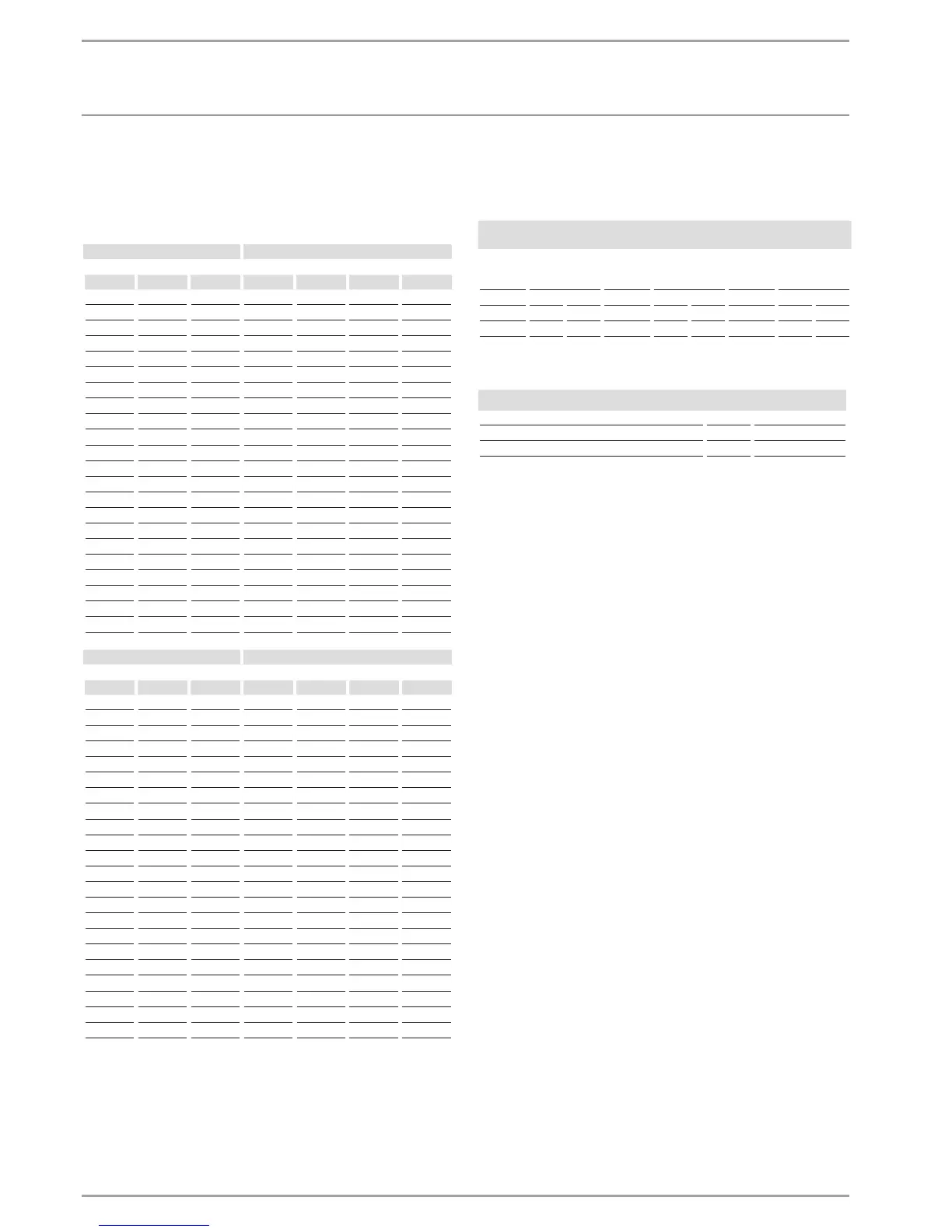
15.3 DHW output
The DHW output is subject to the mains voltage, the appliance’s
connected load and the cold water inlet temperature. The rated
voltage and rated output can be found on the type plate (see
chapter “Operation / Troubleshooting”).
Connected load in kW 38 °C DHW output in l/min.
Rated voltage Cold water inlet temperature
380 V 400 V 415 V 5°C 10°C 15°C 20°C
10.1 4.4 5.2 6.3 8.0
11.0 4.8 5.6 6.8 8.7
12.0 5.2 6.1 7.5 9.5
12.2 5.3 6.2 7.6 9.7
13.2 5.7 6.7 8.2 10.5
13.5 5.8 6.9 8.4 10.7
13.6 5.9 6.9 8.4 10.8
14.2 6.1 7.2 8.8 11.3
14.5 6.3 7.4 9.0 11.5
15.0 6.5 7.7 9.3 11.9
16.2 16.2 7.0 8.3 10.1 12.9
16.3 7.1 8.3 10.1 12.9
18.0 7.8 9.2 11.2 14.3
19.0 8.2 9.7 11.8 15.1
19.4 8.4 9.9 12.0 15.4
21.0 9.1 10.7 13.0 16.7
21.7 9.4 11.1 13.5 17.2
22.6 9.8 11.5 14.0 17.9
23.5 10.2 12.0 14.6 18.7
24.0 10.4 12.2 14.9 19.0
24.4 10.6 12.4 15.2 19.4
25.8 11.2 13.2 16.0 20.5
Connected load in kW 50 °C DHW output in l/min.
Rated voltage Cold water inlet temperature
380 V 400 V 415 V 5°C 10°C 15°C 20°C
10.1 3.2 3.6 4.1 4.8
11.0 3.5 3.9 4.5 5.2
12.0 3.8 4.3 4.9 5.7
12.2 3.9 4.4 5.0 5.8
13.2 4.2 4.7 5.4 6.3
13.5 4.3 4.8 5.5 6.4
13.6 4.3 4.9 5.6 6.5
14.2 4.5 5.1 5.8 6.8
14.5 4.6 5.2 5.9 6.9
15.0 4.8 5.4 6.1 7.1
16.2 16.2 5.1 5.8 6.6 7.7
16.3 5.2 5.8 6.7 7.8
18.0 5.7 6.4 7.3 8.6
19.0 6.0 6.8 7.8 9.0
19.4 6.2 6.9 7.9 9.2
21.0 6.7 7.5 8.6 10.0
21.7 6.9 7.8 8.9 10.3
22.6 7.2 8.1 9.2 10.8
23.5 7.5 8.4 9.6 11.2
24.0 7.6 8.6 9.8 11.4
24.4 7.7 8.7 10.0 11.6
25.8 8.2 9.2 10.5 12.3
15.4 Application areas/ conversion table
Specific electrical resistance and specific electrical conductivity
(see chapter “Installation/ Specification/ Data table”).
Standard specification
at 15 °C
20°C
25°C
Spec. re-
sistance
ρ ≥
Spec. conduc-
tivity σ ≤
Spec. re-
sistance
ρ ≥
Spec. conduc-
tivity σ ≤
Spec. re-
sistance
ρ ≥
Spec. conduc-
tivity σ ≤
Ωcm mS/m μS/cm Ωcm mS/m μS/cm Ωcm mS/m μS/cm
1100 91 909 970 103 1031 895 112 1117
1200 83 833 1070 93 935 985 102 1015
15.5 Pressure drop
Pressure drop at taps at flow rate of 10 l/min
Mono-lever mixer tap. approx. MPa 0.04 - 0.08
Thermostatic valve. approx. MPa 0.03 - 0.05
Hand shower. approx. MPa 0.03 - 0.15
Sizing the pipework
When calculating the size of the pipework. a pressure drop for the
appliance of 0.1MPa is recommended.
15.6 Fault conditions
In case of faults. loads up to a maximum of 95 °C at a pressure of
1.2 MPa can occur temporarily in the installation.
 Loading...