46
ENGLISH
EN
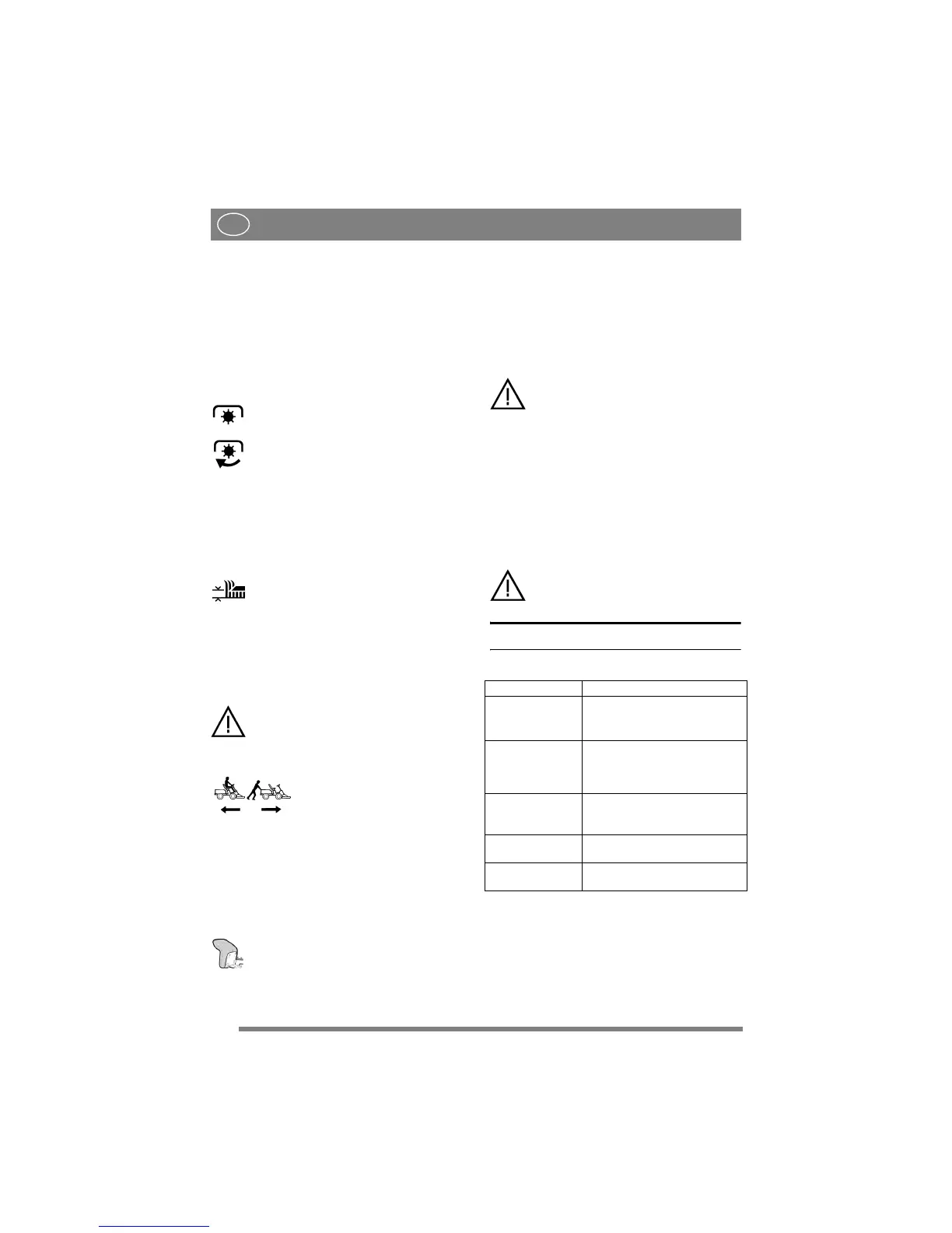
NOTE! You must make sure the machine is quite
stationary before changing from reverse to forward
gear or vice versa. If a gear does not engage im-
mediately, release the clutch pedal and then press
it in once again. Engage the gear once again. Never
force a gear in.
2.4.10 Power take-off (2; 4:E)
A lever for engaging and disengaging the power
take-off for operating cutting decks and front-
mounted accessories. Two positions:
1.Forward position – power take-off dis-
engaged.
2. Backward position – power take-off en-
gaged.
2.4.11 Cutting height adjustment (2:I)
(HST)
The machine is equipped with a control for using
the cutting deck with electrical cutting height ad-
justment.
The switch is used to adjust the cutting
height in continuously variable positions.
The cutting deck is connected to the contact (2:Z).
2.4.12 Clutch release lever (5:K)
A lever for disengaging the variable transmission.
Enables the machine to be moved by hand without
the help of the engine.
The disengagement lever must never be
between the outer and inner positions.
This overheats and damages the trans-
mission.
Two positions:
1. Lever out – transmission en-
gaged for normal operation.
There is an audible click when
the lever locks in the outer posi-
tion.
2. Lever in – transmission disen-
gaged. The machine can be
moved by hand.
The machine may not be towed over long distances
or at high speeds. The transmission could be dam-
aged.
2.4.13 Seat (6:L)
The seat can be folded and adjusted for-
wards and backwards. The seat’s forward/
backward position can be locked with the
knobs (6:M).
The seat is equipped with a safety switch that is
connected to the machine’s safety system. This
means that certain activities that can entail danger
cannot be carried out when nobody is sitting in the
seat. See also 4.3.2.
2.4.14 Engine casing (fig. 7)
To fill with fuel and to inspect and maintain the en-
gine and battery, open the engine casing.
The engine must not be running when
the casing is opened.
2.4.14.1Opening
1. Ensure that the control arms are in their forward
positions.
2. Raise the seat lock (6:N) and fold the seat for-
wards.
3. Grasp the front edge of the engine casing and
fold up the casing (fig. 3).
2.4.14.2Closing
Grasp the front edge of the engine casing and fold
down the casing.
The machine may not be operated un-
less the engine casing is folded down.
Risk of burns and crushing injuries.
3 AREAS OF USE
The machine may only be used for the following
tasks using the genuine STIGA accessories stated.
The maximum vertical load on the towing hitch
must not exceed 100 N.
The maximum over-run load on the towing hitch
from towed accessories must not exceed 500 N.
NOTE! Before using a trailer – contact your insur-
ance company.
NOTE! This machine is not intended to be driven
on public roads.
Work Accessories, STIGA genuine
Mowing Using mowing decks:
85 C, 95 C (HST),
95 C El (16 HST)
Sweeping Using brush unit or collector
brush unit. The use of a dust
guard is recommended with the
first option.
Snow clearance Using snow blade or snow
thrower Snow chains and frame
weights are recommended.
Grass clipping and
leaf collection
Using towed collector 30" or
42".
Grass and leaf
transport
Using dump cart Standard.
 Loading...