53
ENGLISH
EN
1 GENERAL
This symbol indicates WARNING. Seri-
ous personal injury and/or damage to
property may result if the instructions
are not followed carefully.
You must read these instructions for use
and the accompanying pamphlet
“SAFETY INSTRUCTIONS” careful-
ly, before starting up the machine.
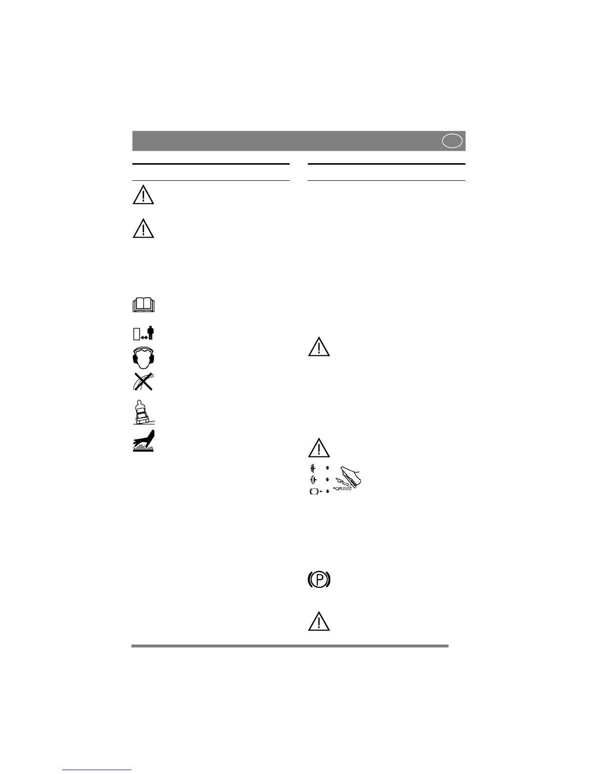
1.1 SYMBOLS
The following symbols appear on the machine.
They are there to remind you of the care and atten-
tion required during use and maintenance.
This is what the symbols mean:
Warning!
Read the instruction manual and the safety
manual before using the machine.
Warning!
Watch out for discarded objects. Keep on-
lookers away.
Warning!
Always wear hearing protectors.
Warning!
This machine is not designed to be driven
on public roads.
Warning!
The machine must not be driven in any di-
rection on slopes with a gradient greater
than 10º.
Warning!
Risk of burn injuries. Do not touch the si-
lencer/catalytic converter.
1.2 References
1.2.1 Figures
The figures in these instructions for use are num-
bered 1, 2, 3, etc.
Components shown in the figures are marked A, B,
C, etc.
A reference to component C in figure 2 is written
as follows:
“See fig. 2:C.” or simply “(2:C)”
1.2.2 Headings
The headings in these instructions for use are num-
bered in accordance with the following example:
“1.3.1 General safety check” is a subheading to
“1.3 Safety checks” and is included under this
heading.
When referring to headings, only the number of the
heading is normally specified. E.g. “See 1.3.1”.
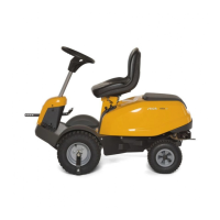
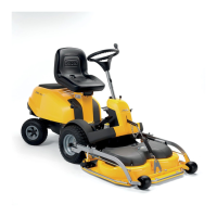
2 DESCRIPTION
2.1 Drive
The machine has front-wheel drive.
Front-mounted implements are powered via drive
belts.
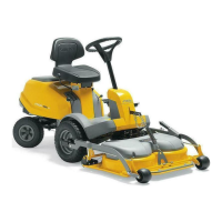
2.2 Steering
The machine has rear-wheel steering. The rear-
wheel steering means that the machine can easily
turn around trees and other obstacles. Steering is
controlled via a wire (Comfort and de Luxe) or
wire-chain (Royal).
2.3 Safety system
The machine is equipped with an electrical safety
system. The safety system interrupts certain activ-
ities that can entail a danger of incorrect manoeu-
vres. For example, the engine cannot be started if
the clutch-parking brake pedal is depressed.
The operation of the safety system must
always be checked every time before
use.
2.4 Controls
2.4.1 Implement lifter, mechanical (2:C)
To switch between working position and transport
position:
1. Depress the pedal fully.
2. Release the pedal slowly.
2.4.2 Clutch-parking brake (2:B)
Never press the pedal while driving.
There is a risk of overheating in the
power transmission.
The pedal (2:B) has the follow-
ing three positions:
• Released. The clutch is not activated. The park-
ing brake is not activated.
• Depressed halfway. Forward drive disengaged.
The parking brake is not activated.
• Pressed down. Forward drive disengaged. The
parking brake is fully activated but not locked.
2.4.3 Inhibitor, parking brake (2:A)
The inhibitor locks the “clutch-brake”
pedal in the depressed position. This func-
tion is used to lock the machine on slopes,
during transport, etc., when the engine is
not running.
The parking brake must always be re-
leased during operation.
 Loading...