52 Series 4180 Powerhead
The ignition module accommodates
all the components required to
control ignition timing.
There are three electrical
connections on the coil body:
: High voltage output with ignition
lead (1)
: Connector tag (2) for the short
circuit wire
: Connector tag (3) for the ground
wire
Accurate testing of the ignition
module is only possible with special
test equipment.
For this reason it is only necessary
to carry out a spark test in the
workshop.
A new ignition module must be
installed if no ignition spark is
obtained (after checking that wiring
and stop switch are in good
condition).
Ignition timing is not adjustable.
Since there is no mechanical wear
in these systems, ignition timing
cannot get out of adjustment during
operation. However, an internal fault
in the circuit can alter the switching
point in such a way that a spark test
will still show the system to be in
order although timing is outside the
permissible tolerance. This will
impair engine starting and running
behavior.
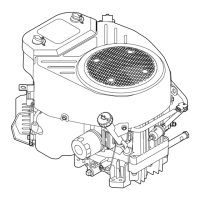
– Remove the shroud, b 5.7
: Disconnect throttle cable nipple
(1) from slotted pin (2) on the
throttle lever.
: Pry the cable (1) out of the spacer
flange.
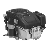
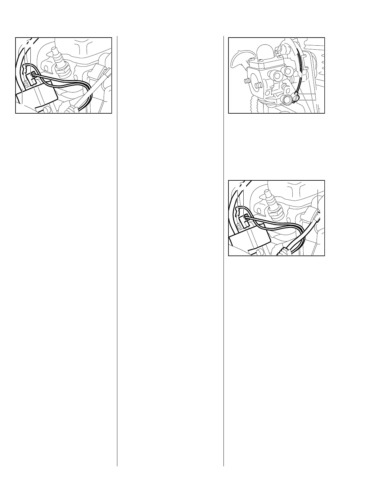
: Pull the short-circuit wire (2) and
ground wire (3) off the ignition
module.
8.2 Ignition Module 8.2.1 Ignition Timing 8.2.2 Removing and Installing
 Loading...