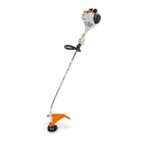
6.4.2 Mounting Shredder Blade
► Shut off the engine.
► Place the thrust plate (5) on the shaft (6) so
that its smaller diameter faces up.
► Place the metal cutting attachment (4) on the
thrust plate (5). If a shredder bladee is used:
Align cutting edges so that they point away
from the gear unit in the direction of the nut
(1).
► Place the thrust washer (3) on the metal cut‐
ting attachment (4) so that its raised side faces
up.
► Place the protective ring (2) on the thrust
washer (3) so that the opening points
upwards.
► Insert the stop pin (7) in the bore as far as
stop and hold it depressed.
► Rotate the metal cutting attachment (4) coun‐
terclockwise until the stop pin (7) engages in
position.
The shaft (6) is now blocked.
► Fit the nut (1) counterclockwise and tighten it
down firmly.
► Remove the stop pin (7).
6.4.3 Removing the metal cutting attach‐
ment
► Shut off the engine.
► Insert the stop pin in the bore up to the limit
stop and hold it depressed.
► Rotate the metal cutting attachment clockwise
until the stop pin engages in position.
The shaft is now blocked.
► Unscrew the mounting nut clockwise.
► Remove the fastening parts, metal cutting tool
and pressure plate.
► Remove the stop pin.
7 Adjusting Trimmer for User
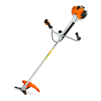
7.1 Fitting and Adjusting the Full
Harness
► Putting on the Full harness (1).
► Adjust the full harness (1) so that the carabi‐
ner (2) is about a hand’s width below your
right hip.
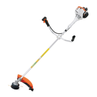
7.2 Adjusting the Bike Handle
The bike handle can be set to different positions
to suit the height and reach of the user.
► Shut off the engine.
► Hook the brushcutter from the carrying strip
into the carabiner of the carrying system.
► Loosen the wing screw (1).
► Swing the bike handle (2) to the required posi‐
tion.
► Tighten down the wing screw (1) firmly.
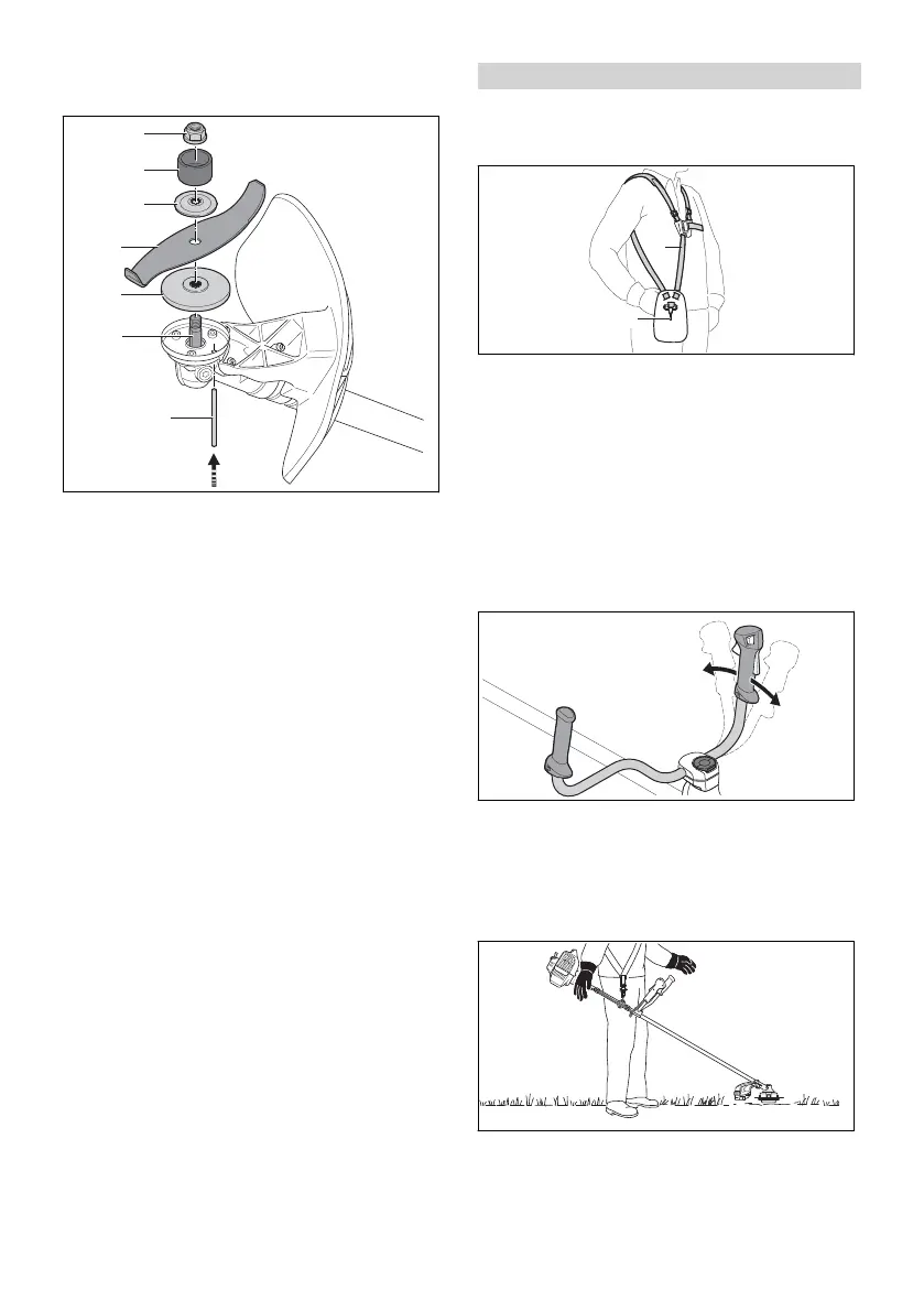
7.3 Balancing the Brushcutter
The cutting attachment should rest lightly on the
ground.
► Shut off the engine.
7 Adjusting Trimmer for User English
0458-844-0101-A 13
 Loading...